EasyManua.ls Logo

Lenze i550 - User Manual

Lenze i550
48 pages
Print Icon
To Next Page IconTo Next Page
Loading...
Operating instructions i550 cabinet frequency inverter | 1
© 11/2021 · EN · www.Lenze.com
Contents
i550 cabinet frequency inverter
0.25 ... 132 kW
Operating instructions

Other manuals for Lenze i550

Questions and Answers

  • M
    Michael LynchSep 1, 2025
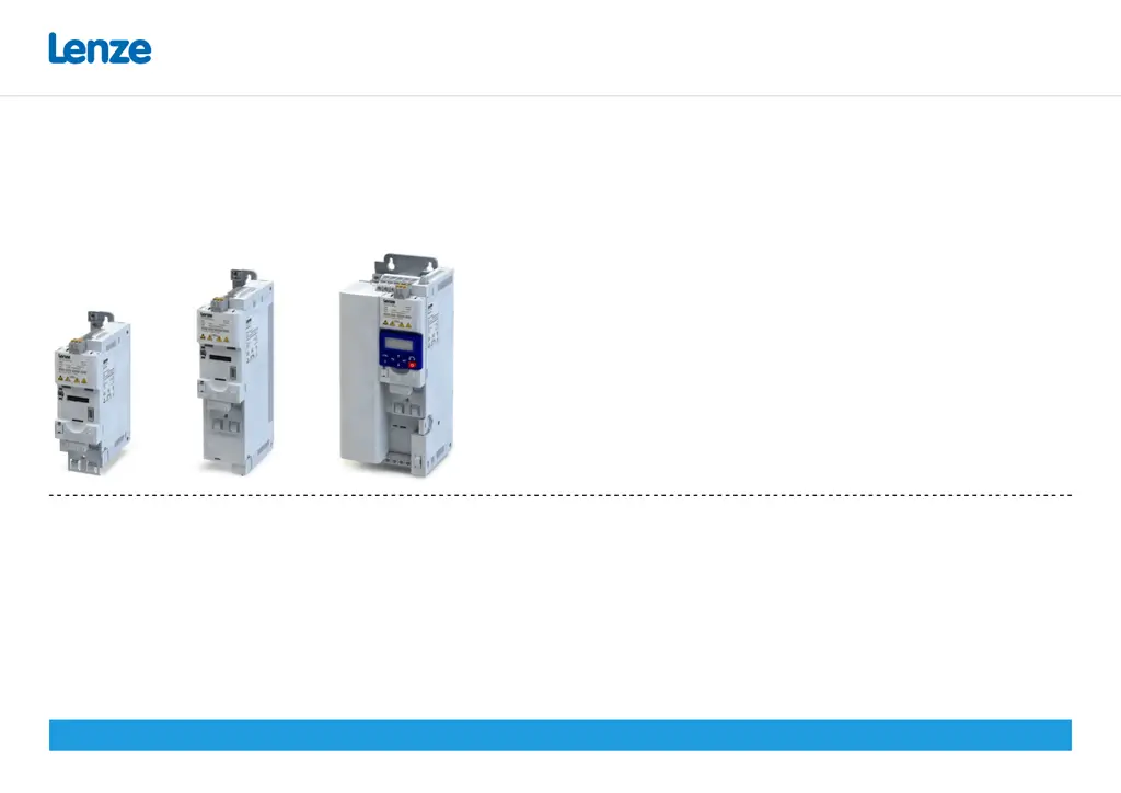
    What to do if my Lenze i550 is overheating?
    • A
      Angela CardenasSep 1, 2025
      If your Lenze Inverter is showing an overtemperature fault, you should: * Check mains voltage. * Provide for a sufficient cooling of the device (display of the heatsink temperature in P117.01). * Clean fan and ventilation slots. If required, replace fan. * Reduce switching frequency (P305.00).
  • D
    Donna ReidSep 1, 2025
    What to do if my Lenze i550 Inverter displays a heatsink fan warning?
    • J
      john79Sep 2, 2025
      If your Lenze Inverter displays a heatsink fan warning, you should: * Clean fan and ventilation slots. If required, replace fan. The fans can be unlocked via locking hooks and can then be removed.
  • A
    Allen AdamsSep 2, 2025
    What to do if my Lenze Inverter shows a 24-V supply fault?
    • A
      Ashley HarrisSep 2, 2025
      If your Lenze Inverter shows a 24-V supply fault, you should: * Check optional external 24-V voltage supply (terminal X3/24E), if connected. * Check mains voltage.
  • M
    millermarieSep 3, 2025
    What to do if my Lenze i550 shows a 24-V supply overload?
    • J
      Justin McdowellSep 3, 2025
      If your Lenze Inverter is showing a 24-V supply overload, you should check the 24-V output and digital outputs for earth fault or overload.
  • A
    Andrea PerkinsSep 3, 2025
    What to do if my Lenze i550 indicates 'Trigger/functions connected incorrectly'?
    • R
      Richard BranchSep 3, 2025
      If your Lenze Inverter indicates that triggers or functions are connected incorrectly, you should: * Check and correct the assignment of the triggers to the functions. * With keypad or network control, the two functions “Inverter enable” (P400.01) and “Run” (P400.02) can also be set to “Constant TRUE [1]” to start the motor.
  • C
    casey69Sep 4, 2025
    What should I do if my Lenze i550 keypad is removed?
    • K
      Katherine HolmesSep 4, 2025
      If the keypad is removed from your Lenze Inverter, plug the keypad back in or activate another control source.
  • R
    Robert MirandaSep 4, 2025
    What to do if my Lenze i550 shows brake resistor overload?
    • K
      Kristina OdomSep 4, 2025
      If your Lenze Inverter displays a brake resistor overload, you should: * Check drive sizing. * Check settings for the braking energy management. Note! The error will be reset if the thermal load falls below the error threshold (P707.09) of - 20 %.
  • M
    Mason ContrerasSep 5, 2025
    What to do if my Lenze Inverter experiences motor overspeed?
    • A
      andrewwilcoxSep 5, 2025
      If your Lenze Inverter experiences motor overspeed, adapt the maximum motor speed (P322.00) and the error threshold (P350.01).
  • R
    Richard StewartSep 5, 2025
    What to do if my Lenze i550 Inverter displays 'Automatic start disabled'?
    • C
      Cynthia AndersonSep 6, 2025
      If your Lenze Inverter displays 'Automatic start disabled', deactivate the start command and reset the error.
  • E
    Ernest GrossSep 6, 2025
    What does 'Keypad full control active' mean on my Lenze i550 Inverter and how do I exit?
    • A
      anneruizSep 6, 2025
      If your Lenze Inverter indicates that 'Keypad full control' is active, press the keypad key to exit the control mode.

Summary

General Information

Hardware Overview of the Inverter

Overview of the inverter's physical components and connections.

Application as Directed

Specifies the intended use and limitations of the product.

Device-Specific Standards and Directives

Lists relevant safety and technical standards the product adheres to.

Relevant Standards and Directives for the Operator

Outlines operator responsibilities regarding standards and directives.

Commissioning Requirements

Details requirements for safe and compliant product commissioning.

PROFINET Licence Information

Information on the PROFINET firmware and its licensing.

Product Identification

Explains how to identify different product variants and their coding.

Numeric Notation

Defines the use of decimal separators in the documentation.

Design of Safety Instructions

Explains the meaning and importance of safety instruction symbols and levels.

Safety Instructions

Basic Safety Precautions

Essential safety precautions to prevent injury and damage.

Residual Hazards

Identifies hazards that remain after safety measures are applied.

Technical Data

Standards and Operating Conditions

Specifies approvals, standards, and environmental operating conditions.

Mechanical Installation

Important Installation Notes

Crucial considerations before and during mechanical installation.

Shield Connection Sheet Mounting

Instructions for attaching the shield connection sheet to the mounting plate.

Dimensions and Assembly

Provides dimensional data and assembly requirements for the inverters.

Electrical Installation

Preparation for IT System Connection

Specific preparation steps for connecting to an IT system.

Connection Diagram

Illustrates exemplary wiring for all voltage and power classes.

EMC-Compliant Installation

Guidelines for ensuring electromagnetic compatibility during installation.

1-Phase Mains Connection 120 V

Technical data and fusing for 1-phase, 120V connections.

1-Phase Mains Connection 230;240 V

Technical data and fusing for 1-phase, 230/240V connections.

3-Phase Mains Connection 230;240 V

Technical data and fusing for 3-phase, 230/240V connections.

3-Phase Mains Connection 400 V (0.37-7.5 kW)

Technical data and fusing for 3-phase, 400V connections.

3-Phase Mains Connection 400 V (7.5-132 kW)

Technical data and fusing for 3-phase, 400V connections.

3-Phase Mains Connection 480 V (0.37-7.5 kW)

Technical data and fusing for 3-phase, 480V connections.

3-Phase Mains Connection 480 V (7.5-132 kW)

Technical data and fusing for 3-phase, 480V connections.

Brake Resistor Connection

Instructions and recommendations for connecting a brake resistor.

Control Terminals X3

Details on the function and connection of control terminals.

Relay Output X9

Information on the relay output terminals and their specifications.

PTC Input X109

Details on the PTC input for motor temperature monitoring.

Networks Configuration

Configuration for various network communication protocols.

Functional Safety Requirements

Critical safety information and requirements for functional safety.

Safe Torque Off (STO) Function

Explanation and implementation of the Safe Torque Off (STO) function.

Commissioning

Initial Switch-On Procedure

Steps for the first-time power-up and initial checks.

Important Commissioning Notes

Key considerations and warnings during the commissioning process.

Keypad Module Functions

Explains the operation of the keypad and its keys for parameter control.

Keypad Control Activation

How to activate and use keypad control for motor operations.

Quick Commissioning via Terminal Control

A streamlined process for commissioning using terminal controls.

Extended Terminal Control Wiring

Detailed wiring and parameter configuration for terminal control.

Key Parameters Overview

Overview of key parameters and their grouping for efficient setup.

Favorites (Group 0)

Commonly used parameters configurable as favorites for quick access.

Basic Setting (Group 2)

Essential parameters for basic configuration and operation.

Motor Control (Group 3)

Parameters related to motor identification, calibration, and data.

Additional Functions (Group 7)

Parameters for loading default settings and saving user data.

Troubleshooting

Error Message Display

How to interpret and display error messages on the keypad.

Error Codes and Remedies

A comprehensive list of error codes, their descriptions, classifications, and remedies.

LED Status Indicators

Explains the meaning of the status LEDs for the inverter.

Support and Further Information

Information on how to obtain further support and product details.

Disposal

Lenze i550 Specifications

General IconGeneral
Protection ClassIP20
Overload Capacity150% for 60 seconds
SafetySTO (Safe Torque Off)
Voltage Range380 V to 480 V
Control TypeVector control, V/f control
Communication InterfacesCANopen, EtherCAT, PROFINET, Ethernet/IP
Mains Voltage3-phase 380 V to 480 V
Input Voltage3-phase 380 V to 480 V
Output Voltage0 to Mains Voltage
Frequency Range0 Hz to 300 Hz
Protection FeaturesOvercurrent, overvoltage, undervoltage, short circuit, overtemperature
Ambient Temperature-10°C to 50°C

Related product manuals