Hazardous voltage may be present.
Always isolate the electrical power supply before making or changing
connections to the unit.
In case of the usage of an inadequate AC/DC power supply, mains
voltages may be present (even if the system is designed for 48VDC).
The usage of a galvanic separated power supply, which is certified by
a 3
rd
party (UL or CE), is highly recommended.
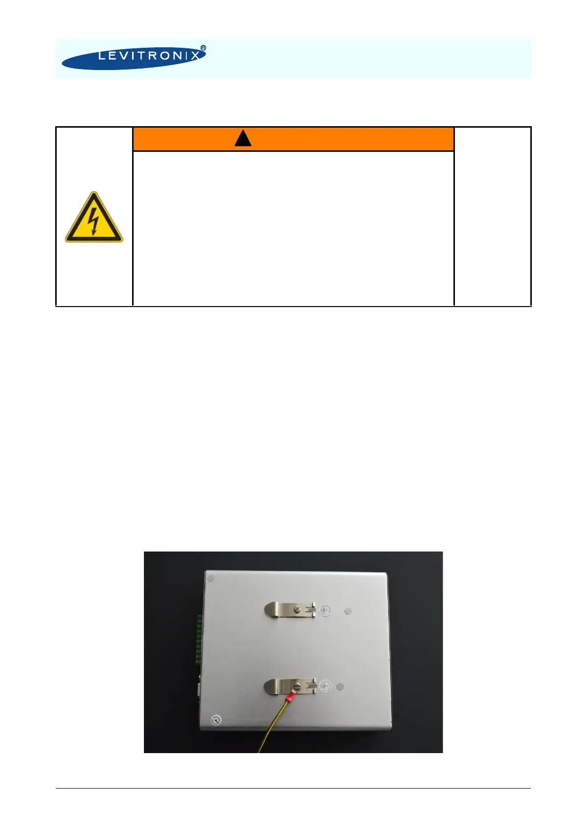
The controller housing must be properly grounded and placed in a spill
protected electrical cabinet. Use one of the DIN-rail screws on the back
side of the controller housing.
Do not use different and longer screws, which may result in short-
circuit within the controller.
1. The controller and the power supply casings must be grounded. The screws of the DIN-rail
bracket can be used for grounding (see Figure 11).
2. Connect the two motor connectors (“POWER OUTPUT” and “SENSORIC”) to the controller.
3. Section 4.1.3 describes the installation for standalone operation with the user panel and
Section 4.1.4 describes extended operation with external PLC signals. For control with
external signal connect the “USER INTERFACE” connector according to Figure 12 and Figure
13.
4. The pump system requires 48 VDC supply voltage at a maximum power of 300 W. Depending
on the hydraulic operational point power supplies with smaller power or bigger supplies to
supply several pump systems simultaneously may be used. Figure 7 shows the power
consumption depending on the pressure and flow rate. Contact Levitronix for consulting and
support on the power supply solution.
5. Connect the DC power supply connector with the cable (included in the controller delivery).
Make sure that the polarity is correct (see Figure 10 ) and that AC/DC power supply is off.
6. To secure the connectors, tighten all retaining screws according to the torque specification in
Table 7.
Figure 11: Grounding of controller LPC-300.1