User Manual for BPS-300
www.levitronix.com
PL-4006-00, Rev07, DCO# 20-144
4 Installation
4.1 Electrical Installation of Controller
4.1.1 Overview
The LPC-300.1 controller has signal processor controlled power converters with switched inverters for the
drive and the bearing coils of the motor. The signal processor allows precise control of pump speed and
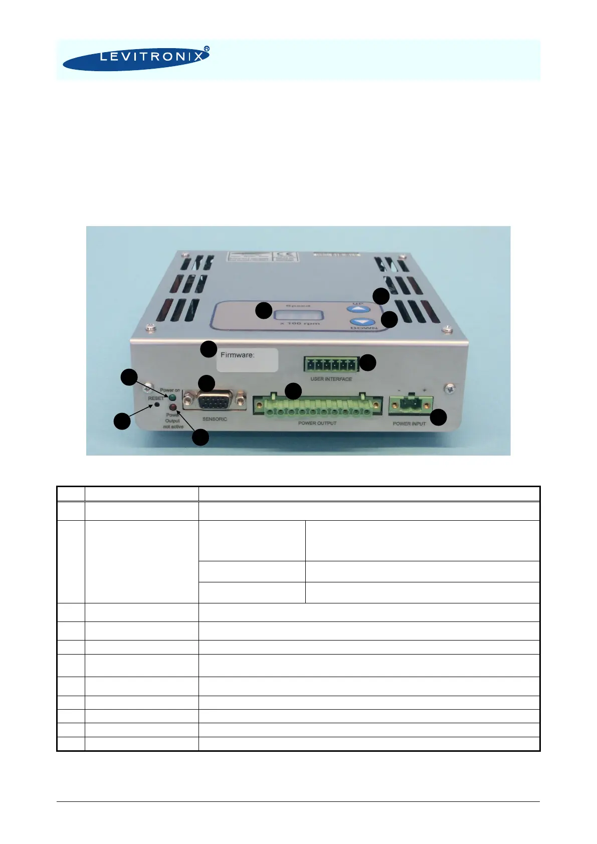
impeller position. Figure 10 shows the interfaces of the standalone controller LPC-300.1 with stand-alone
and minimal PLC functions.
Figure 10: Overview of the controller LPC-300.1 for standalone operation
Position, field and temperature sensor signals from motor
Torque spec. for tightening of connector screws: Min. = 0.4, Max. = 0.6 Nm
- Galvanic isolation with optocoupler
- Lowest input voltage for high level detection: min. 5 V
Typical 24 V / 16 mA, maximal 30 V / 20 mA
- Highest input voltage for low level detection: max. 0.8 V
- Minimum input resistance: R
IN
= 2.2 k
- Galvanic isolation with relay
- Relay: 1A / 30VDC, 0.3A / 125 VAC
- Analog current input: 4 – 20 mA
- 450 Ohm shunt input
Drive and bearing currents of the motor
1
Torque spec. for tightening of connector screws on motor side: Min. = 0.5 Nm, Max. = 0.6 Nm
DC power input
1
Torque spec. for tightening of connector screws on motor side: Min. = 0.5 Nm, Max. = 0.6 Nm
LED is on if supply voltage of signal electronics is present.
“Power Output not active”
Red LED
Red LED is off if the switched output stage of the controller is enabled. If the LED is on, the bearing and
drive coils of the motor carry no current.
Reset button of the controller stage. The button is sunk mounted and can be activated for example with a
small screw driver.
Rotational speed display in 100rpm
Button for speed increasing
Button for speed decreasing
Firmware version and revision number
Table 7: Description of interfaces of LPC-300.1 controller
1: Connectors are not made for multiple connection cycles. Avoid connections cycles > 25.