5.2 Standalone Operation (Button Control Mode)
▪ When applying power the system defaults into the “Button Control Mode” and goes into the status “OFF
ButtonControl” according to Figure 14. Levitation is disabled and the display indicates “OF”.
▪ Levitation can be enable by pressing the “UP” button during 1 second (display shortly indicates “ON”) or
by activating (typically 24V) the “ENABLE” pin on the “USER INTERFACE” connector (see Table 8). The
system goes then into the status “ON Button Control” and is running at the speed which is stored in the
EEPROM.
▪ The speed can be changed by pressing accordingly the “UP” and “DOWN” buttons.
As long as the digits on the display are blinking the set speed is shown. As soon as blinking stops the
actual speed is shown and the set-speed is stored in the EEPROM of the controller after about 2
seconds.
▪ The system can be disabled by pressing the “DOWN” button until 0 rpm is achieved. Pressing further 1
second the “DOWN” button the system disables levitation and shows “OF” on the display. The system
can also be disabled by deactivating (0 V) the “ENABLE” pin on the “USER INTERFACE” connector (see
Table 8). Before disabling the system the speed is automatically reduced to 0 rpm and the impeller is
properly touched down without grinding the wall.
▪ In case of an error the “RESET” button (see Table 7) can be used to restart the system or the power can
be switch off and on. For more detailed error analysis the codes described in Table 9 are shown (blinking
between “Er” and the according code number) on the display.
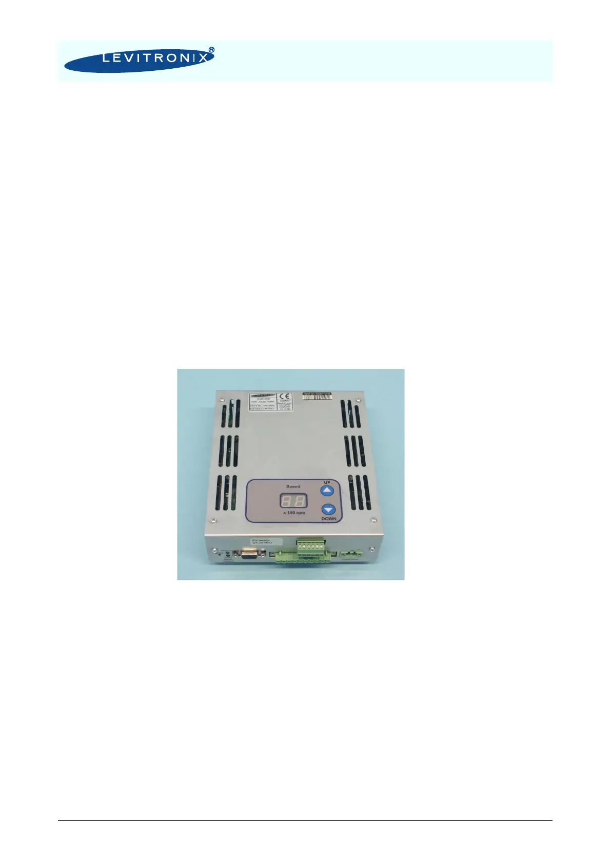
Figure 15: User Panel of LPC-300.1
5.3 Extended Operation (“Analog Control Mode”)
▪ In order to be able to control the pump with external signals (PLC) the mode “Analoge Control Mode” has
to be set with the display buttons. The “UP” and “Down” buttons have to be pressed simultaneously
during 5 seconds. The display should feedback the change by blinking between the stored speed value
and “An”. The chosen mode is then stored in the EEPROM of the controller.
▪ The system and levitation can be enabled/disabled with the digital input on the “USER INTERFACE”
connector (see Table 8). When disabling the running system the speed is automatically reduced to 0 rpm
and the impeller is properly touched down without grinding the wall.
▪ The speed can be set with an analoge signal on the “USER INTERFACE” connector according to Table
8. It is strongly recommended to use galvanic separated signal values
▪ For monitoring purposes a digital output on the “USER INTERFACE” connector (see Table 8) indicates
an error. In case of an error the codes described in Table 9 are displayed (blinking between “An” and the
according code number)