User Manual for BPS-4000
www.levitronix.com
PL-4016-00, Rev11, DCO# 18-057
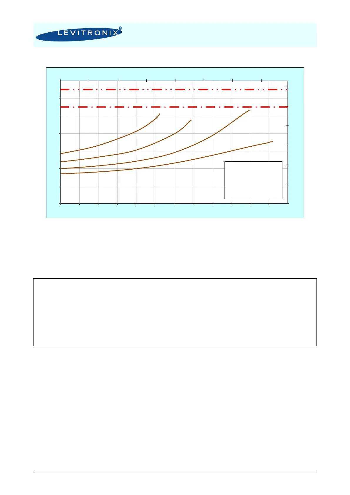
Figure 20: Temperature curves of motor LPM-4000.2 with Air Cooling Module ACM-4000.1 & 3
Temperature is measured inside of the motor, temp. of housing is significantly below this temperature.
Typical curves measured with pump head LPP-4000.5.
The above curves are measurements of the motor temperature at certain liquid and ambient temperatures.
Equation (Eq. 1) shows how to calculate the motor temperature for other liquid and ambient temperatures
based on these curves.
)()(),(),(
ntAMeasuremeALMntLMeasuremeLntAMeasurementLMeasuremeMALM
TTtgTTTTTTTT −+−+
Temp. Gradiant Liquid/Motor
for ACM-4000.1/3 at 25 °C and 0.9 bar air
All above presented thermal data are typical values, which are partly based on measurements and partly on
interpolations with a simplified thermal model and are therefore only guideline values and are suitable for a
first layout of the basic thermal concept. It is recommended to check the thermal values with the motor
placed on the final location and under worst case performance conditions of the application.
In order to account for thermal variations (like ambient temperature, closed chemical cabinets or corners
without ventilations) and to not significantly reduce the MTBF of the motor it is recommended to keep about
10 to 20 °C safety distance to the absolute thermal limit of the motor (90 °C) when designing the thermal
concept of the pump system.
77
97
117
137
157
177
197
0 10 20 30 40 50 60 70
25
35
45
55
65
75
85
95
0 25 50 75 100 125 150 175 200 225 250 275 300
[F]
[gallons/min]
[°C]
[liters/min]
Ambient Temp = 25C
Liquid Temp. = 40C
Specific gravity = 1 g/cm
3
Viscosity = 0.7 cP
Air cooling with ACM-4000.1
0.9 bar, ~25C air
Absolute Temperature Limit
Recommended Operational Limit