11. Press the pump casing into the Reinforcement
Ring, mount the Axial Support Plate and add
the two Semi Fixation Rings.
12. Tighten the 8 Pump Mounting Screws (with
the relevant washers) crosswise and
symmetric regular on the semi fixation rings
and add the Protective Screw Covers. The
screws should not be used to press the lid
with the O-ring into the bottom of the pump
casing. Do not apply too much torque. The
torque specifications are:
Recommended torque for Pump Mounting Screws:
Stainless Steel M10: 150 Ncm
(PVDF M10: 100 Ncm)
Note: These are typical values for the standard pump head
LPP-4000.5. Refer to the relevant pump head specification drawings
for other configurations, which may have different values.
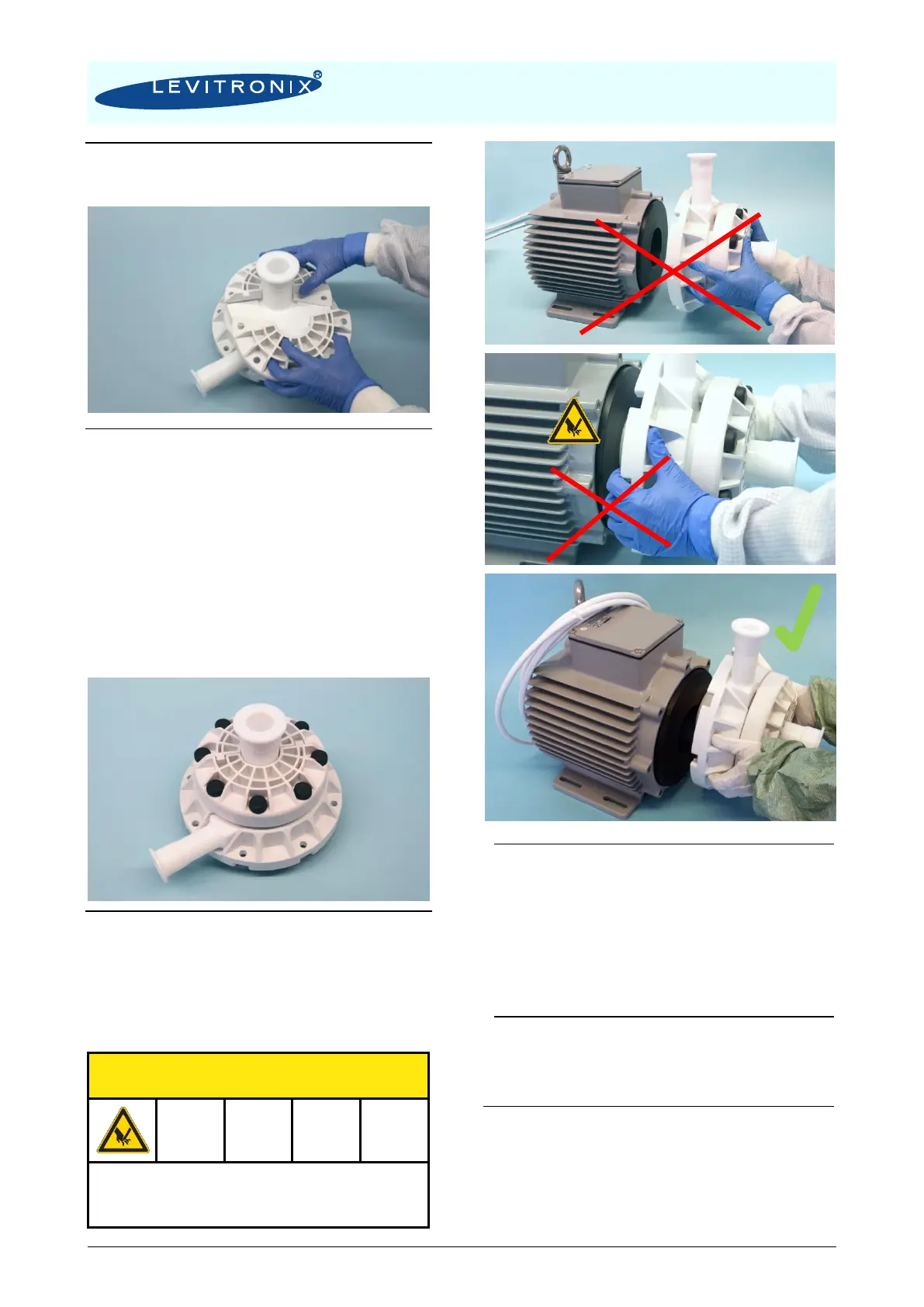
13. Insert the pump casing to the motor by placing
the bottom of the pump head on the side of
the motor cup and move it afterwards to the
center until the pump head locks in. Do not
directly insert the pump head to the center of
the motor as the fingers could be squeezed by
the magnetic forces.
Take care of your fingers. Hold the pump head
on the outer side and not on the bottom
because of risk to get the fingers squeezed.
14. Mount the pump head with the 8 Motor
Mounting Screws crosswise and symmetric
on the motor. Do not apply too much torque.
The torque specification is:
Recommended torque for pump motor screws:
PTFE coated stainless steel M10: 120Ncm
Note: These are typical values for the standard pump head LPP-
4000.5. Refer to the relevant pump head specification drawings for
other configurations, which may have different values.
15. Start the system and check if the Impeller is
rotating properly and the pump head doesn’t
leak.
16. If the pump head leaks, check and make sure
that the Pump Casing Lid and the O-Ring are
properly pressed into the Pump Casing
Bottom. It may be necessary to change the O-
Ring if it has been damaged.