User Manual for LEVIFLOW
®
LFS Flowmeters
www.levitronix.com
PL-4502-00, Rev11, DCO# 18-107
2.4.2 Overview of Parameter Configuration
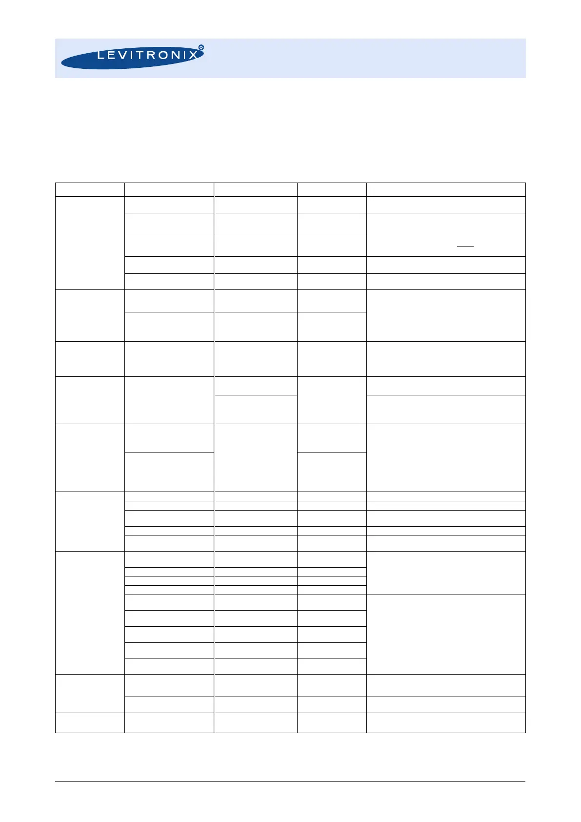
Table 8 shows the standard (“Default”) and possible parameter configurations of the flowmeters. This user
manual is dealing with the standard configuration. For setting up other configurations the LEVIFLOW
®
Configuration Software is needed. Consult the “Configuration-SW User Manual” (Levitronix
Doc.# PL-4501-
00) for more detailed description.
LFS-xx
xx = 04, 08, 20, 50, 80, 008
xx = 008,4,8,20,50,80
(accord. Sensor size)
Default Values:
LFS-008 = 0.8 L/min, LFS-04 = 4 L/min, LFS-08 = 8 L/min
LFS-20 = 20 L/min, LFS-50 = 50 L/min, LFS-80 = 80 L/min
Flow cut to 0 below this percentage of full-scale
If cutoff 0% is chosen, negative flow becomes visible
Kinematic Visc. = Dynamic Visc. / Density
Flow Value in L/min
Flow Value in mL/min
Volume Counter Value
Parameter shown in converter display
0 digits (#.)
1 digits (#.#)
2 digits (#.##)
3 digits (#.###)
Analog output
settings
(Not applicable for
LFC-6C)
Digital input
settings
(Not applicable for
LFC-6C)
Set Volume Counter to zero
Automates zeroing, when liquid type changes
Digital output
settings
(Not applicable for
LFC-6C)
Flow alarm High
Flow alarm Low
Vol. counter alarm H
Vol. counter alarm HH
Vol. counter Pulse
Measurement Error
Flow as Frequency
Bubble detect
Custom Output
- Upper flow limit detection
- Lower flow limit detection
- Flow volume detection first value (one-time)
- Flow volume detection second value
- Pulse per volume
- Error signal (empty sensor etc.)
- Flow as Frequency output (100% of full-scale = 1 kHz)
- Bubble detected signal
- Bits of equipment status can be OR-ed on the output
Can be used to get tolerance to noise.
Alarm setting In percentage of full-scale.
N.O. = normally open
N.C. = normally closed
For digital outputs of LFC-1C, LFC-1C-F4, LFC-6CIO.
Alarm setting In percentage of full-scale.
N.O. = normally open
N.C. = normally closed
For digital outputs of LFC-1C, LFC-1C-F4, LFC-6CIO.
Volume counter enable
(activation box)
These are settings for volume detection (integration of
flow).
Has to be active for the options “ Vol. Counter Alarm H”,
“Vol. Counter Alarm HH” and “Vol. Counter Pulse”.
Volume counter pulse length
Volume counter alarm enable
(activation box)
-> Settings for one-time volume detection.
-> Volume = “Volume unit” x “Multiplier factor” x “Vol.
Counter Alarm H“ value”
-> Has to be active for the options “Vol. Counter Alarm
H”, “Vol. Counter Alarm HH”.
Value
(Volume counter alarm H)
N.O. = normally open
N.C. = normally closed
Value
(Volume counter alarm HH)
N.O. = normally open
N.C. = normally closed
Measurement
Error Settings
Instant Measurement Error
Ignore Time
During this time instant measurement errors are ignored.
If an instant measurement error stays active for longer
time than this time, measurement error arises.
Flow Level on Measurement
Error
Signal level of analog output and flow, when
measurement error arises
Bubble Detection
Settings
For bubble or particle detection in the process
Table 8: Overview of parameters