User Manual for LEVIFLOW
®
LFS Flowmeters
www.levitronix.com
PL-4502-00, Rev11, DCO# 18-107
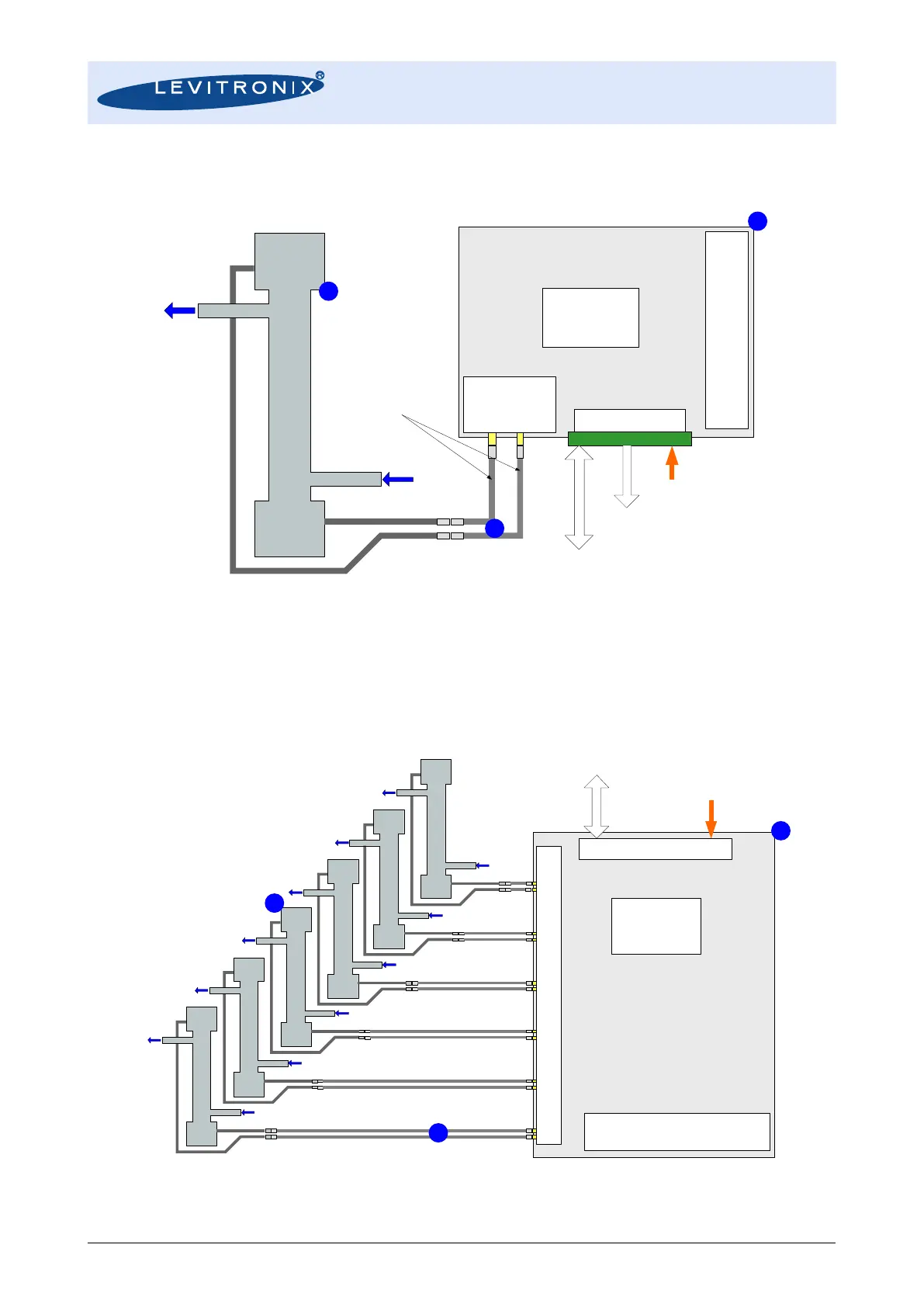
2.2 Standard System Configurations
2.2.1 Single Channel Configuration – LFS-Series
Figure 4: Flowmeter configuration with LFC-1C single channel converter
(For LFS-008 flow sensor special LFC-1C-F4 converter is necessary)
2.2.2 Multi-Channel Configuration – LFS-Series
Figure 5: Flowmeter configuration with LFC-6C converter (6 channel)
(Does not work with LFS-008 flow sensor)
LEVIFLOW
®
Converter LFC-1C
(Single Channel)
4-Digit Display
Zero Adjustment
Adress Setting for RS485
Piezo Transducers
In-/Output
IN OUT
Electrical Interface
Power Supply: 24 VDC
RS485 (MODBUS)
- Configuration with PC Software
- Data Reading
- Fieldbus Array of Multiple Sensors
Analog and Digital Outputs
- 1x Analog Output
- 2x Digital Outputs
- 1x Digital Input
LEVIFLOW
®
Sensor LFS-xx
Flow In
Flow Out
Extension
Cables LFE
Digital
Signal Processor
DSP
LEVIFLOW
®
Converter LFC-6C
(6-Channel)
4-Digit Display
Zero Adjustment
Address Setting for RS485
Piezo Transducers In-/Output
Signal/Power Bus Connector
Power Supply: 24 VDC
RS485 (MODBUS)
- Configuration with PC Software
- Data Reading
Digital
Signal Processor
DSP
Flowsensor LFS
Flowsensor LFS
Flowsensor LFS
Flowsensor LFS
Flowsensor LFS
Flowsensor LFS