User Manual for LEVIFLOW
®
LFS Flowmeters
www.levitronix.com
PL-4502-00, Rev11, DCO# 18-107
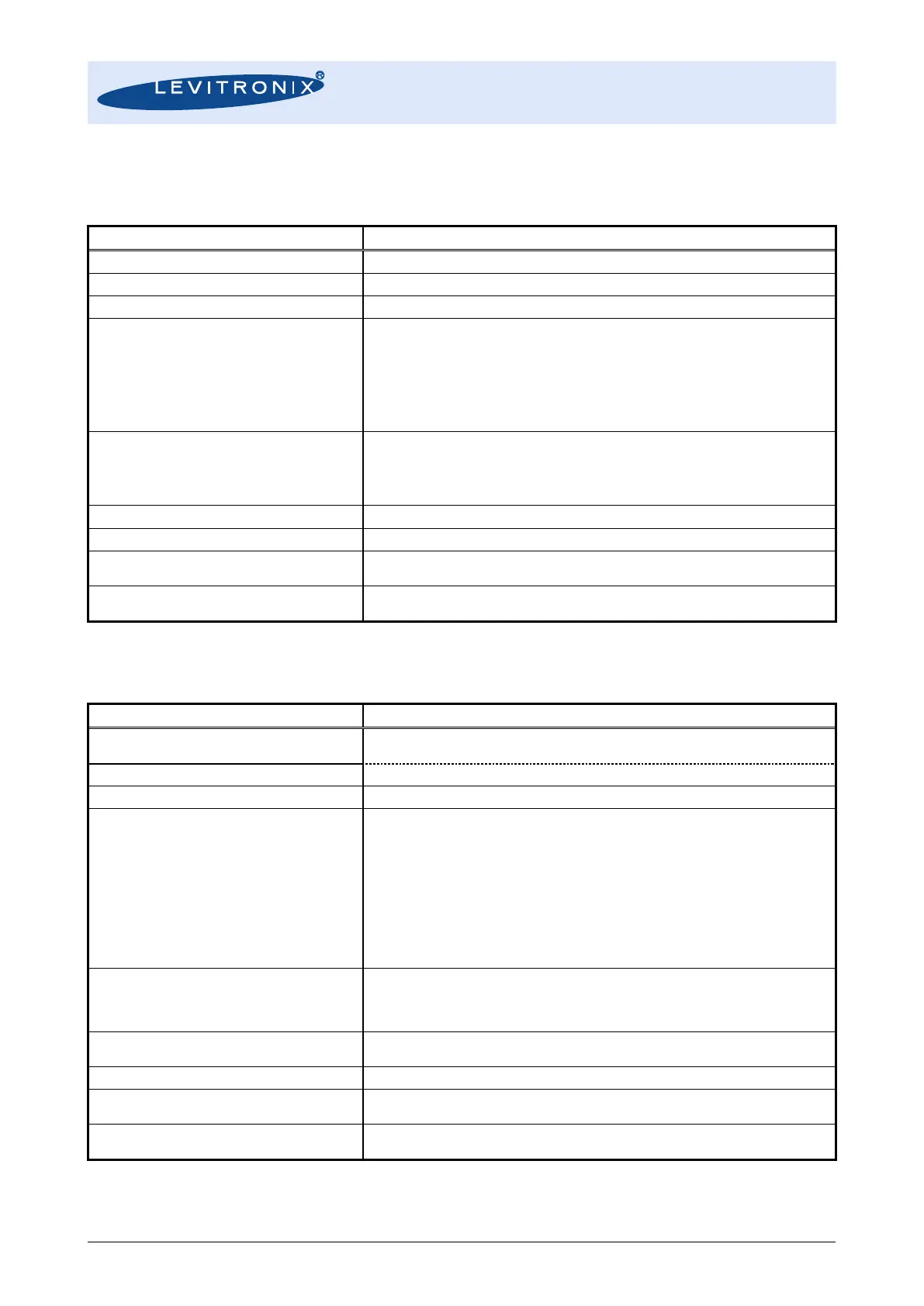
2.4 Specifications of Converters
2.4.1 General Specifications
Single Channel Converter Types LFC-1C and LFC-1C-F4
Power Supply Voltage / Current / Inrush Current
24 VDC ± 10% / 150 mA / Peak 1.8 A within 100 µs
Ambient Temp / Humidity Range
0 – 50 °C (32 – 122 °F) / 30 - 85% R.H. (no condensation)
Enclosure Classification and Material
Interfaces
(see Figure 10 for detailed PIN designation and electrical
specification)
- RS485 -> MODBUS protocol -> max. array of 99 channels
- 1x Analog Output: 4 – 20mA (0 – 20mA configurable)
- 2x Digital Outputs: Flow Alarm, Measurement Error, Volume Counter Pulse, Volume Counter
Alarm, Flow as Frequency or Bubble Detection, Custom Output (default: normally open)
- 1x Digital Input: Volume Counter Reset or Zero Adjust
- 4 Digit display (flow rate, volume counter, error codes), re-zero button
- Address potentiometers for RS485 address setting
Configuration Parameters
(Available and configurable with RS485/USB converter and
configuration software)
- Viscosity
- Low Cutoff,
- Dampening time (filter)
- Full scale setting,
- Linearization (15 points)
- Alarm Outputs (High and Low Alarm)
- Volume Counter and Volume Counter Alarm Settings
Weight / Dimensions / Mounting
130 g / 123 x 75 x 17.5 mm / DIN rail
Duration for Activation of Manual and Digital Zeroing
Duration of Zeroing Procedure
LFC-1C: normal 6 sec , maximum 15 sec
LFC-1C-F4: normal 26 sec, maximum 60 sec.
Duration of Measurement Ready after Power-On
Warm-Up Time for Full Performance Measurements
Table 6: Specifications for single-channel converters LFC-1C and LFC-1C-F4
6-Channel Converter Types LFC-6C and LFC-6CIO
Power Supply Voltage / Current / Inrush Current
LFC-6C : 24 VDC ± 10% / 150 mA / Peak 1.7 within 120 µs
LFC-6CIO : 24 VDC ± 10% / 270 mA / Peak 4.9 within 180 µs
Ambient Temp / Humidity Range
0 – 50 °C (32 – 122 °F) / 30 - 85% R.H. (no condensation)
Enclosure Classification and Material
Interfaces
(see Table 11 for LFC-6C and Table 11/Table 12/Table 13 for
LFC-6CIO for detailed PIN designation and electrical
specification)
- RS485 -> MODBUS protocol -> max. array of 99 ch.
- Stacking of max. 16 converters -> 5 ms DSP process/time per channel
- 4 Digit display (flow rate, volume counter, error codes), re-zero button
- Address potentiometers for RS485 address setting
For LFC-6CIO only:
- 6x Analog Outputs: 4 – 20mA (0 – 20mA configurable)
- 6x Digital Outputs: Flow Alarm, Measurement Error, Volume Counter Pulse, Volume Counter
Alarm, Flow as Frequency or Bubble Detection, Custom Output (default: normally open)
- 6x Digital Input: Volume Counter Reset or Zero Adjust
Configuration Parameters
(Available and configurable with RS485/USB converter and
configuration software)
- Viscosity
- Low Cutoff
- Dampening constant (filter)
- Full scale setting
- Linearization (15 points)
- Alarm Outputs (High and Low Alarm)
- Volume Counter and Volume Counter Alarm Settings
Weight / Dimensions / Mounting
LFC-6C: 170 g / 139 x 77 x 17.5 mm / DIN rail
LFC-6CIO: 182 g / 139 x 77 x 18.5 mm / DIN rail
Duration for Activation of Manual and Digital Zeroing
Duration of Zeroing Procedure
LFC-6C: normal 15 sec, maximum 30 sec.
LFC-6CIO: normal 26 sec, maximum 60 sec.
Duration of Measurement Ready after Power-On
Warm-Up Time for Full Performance Measurements
Table 7: Specifications for multi-channel converters LFC-6C and LFC-6CIO