3.2.2 Instructions for Electrical Installation
1. Remove the DC power from the converter.
2. Remove the interface connector on the connector box (see Figure 17b)
3. Attach the necessary wires (AWG 14-26) according to the pin specifications in Table 11, Table
12 or Table 13. Strip the sheath approximately 3mm from the wires end. Insert the core into
the connector up to the end and tighten the screw. Confirm that the wires are securely fixed
by pulling it by hand.
4. Note: The Field Ground (FG) represents an additional ground potential, which is connected
internally to the signal ports of the converter via varistors. Depending on the specific setup, it
might be advantageous from an EMC perspective to connect the FG to the PE. However, in
case the FG is connected to PE the entire grounding concept of the field installation has to be
considered in order to avoid stray and compensating currents triggered by electrical potential
differences. If compensating currents between PE and Ground may occur, the FG should not
be connected.
5. For usage of a fuse at the power input slow-blow type with a current rating of the converters
(see Table 7) and 25% additional margin is recommended. Consider the inrush current of the
converters (see Table 7) during power start-up, when choosing the fuse type and the AC/DC
power supply.
6. Mount the interface connector to the converter and tighten the 2 connector screws.
7. Before powering on, check again all wiring connections. Confirm that the terminals are
securely fastened and that there is no possibility of short circuit.
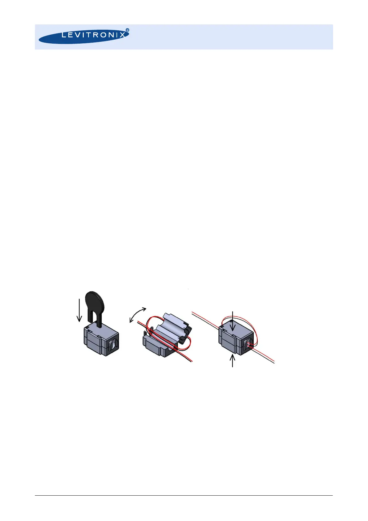
8. For proper EMI behavior of the LFC-6CIO a DC supply ferrite is needed. This can be ordered
according to Table 3 and assembled according to Figure 19. One winding turn shall be
applied and the ferrite shall be placed at a distance not longer than 15 cm from the connector
box of the converter (see also Figure 12).
Figure 19: Mounting of DC supply EMI ferrite for LFC-6CIO
(See Table 3 for order information)
3.2.3 Configuration of Sensor Specific Data
In his standard configuration the multi-channel converters LFC-6C and LFC-6CIO come shipped without
sensor specific data stored. The K-Factor and the Calibration Values of each sensor have to be stored to the
converter with the LEVIFLOW
®
configuration software. The K-Factor and the 5 Calibration Values (11 for
LFS-008) are available on the sensor tag and on a calibration sheet delivered with each sensor.
Consult the configuration “Configuration-SW User Manual” (Levitronix
Doc.# PL-4501-00) for handling with
the LEVIFLOW
®
configuration software.