User Manual for LEVIFLOW
®
LFS Flowmeters
www.levitronix.com
PL-4502-00, Rev11, DCO# 18-107
3.1.4 Instructions for Mechanical Installation
Hazardous voltage may be present.
In order to avoiding fluid spills shorting voltages within the converter,
place it in a spill protected environment (for example protected
electronic cabinets).
If explosive flammable gases are present, place the converter in an
explosion-proof cabinet.
1. The converter shall be installed in a spill protected cabinet.
2. Assure that sufficient ventilation is provided in order to avoid exceeding the allowed ambient
temperature and humidity range:
➔ Temperature range: 0 – 50 °C (32 – 122 °F)
➔ Humidity range: 30 - 85% R.H. (no condensation)
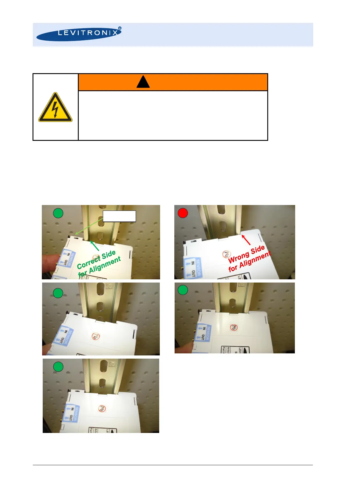
3. Mount the converter on a DIN rail according to the following steps:
Step 1: Align first the Snap-Pin side of the converter
with the DIN rail corner (picture a). If the rigid
side is aligned first (see picture b) than some of
the DIN rail parts of the converter housing might
be damaged.
Step 2: Press in the converter on the spring-pin side
(see picture c).
Step 3: Press in the fix side of the DIN rail recess of the
converter housing (see picture d)
Step 4: Relax the converter and let the snap-pin fix it
(see picture e).
Figure 16: Din Rail mounting steps for converter LFC-1C
(For dis-mounting follow the steps in reverse order)