Home
Levitronix
Measuring Instruments
LEVIFLOW LFC-1C
Levitronix LEVIFLOW LFC-1C User Manual
5
of 1
of 1 rating
31 pages
Give review
Manual
Specs
To Next Page
To Next Page
To Previous Page
To Previous Page
Loading...
User Manual for LEVIFLOW
®
LFS Flowmeters
www.levitronix.com
PL
-
4502
-00, Rev11,
DCO#
18
-
107
11
2.5
Basic Dimension
s of Ma
in Componen
ts
2.5.1
Dimensions of Sensors
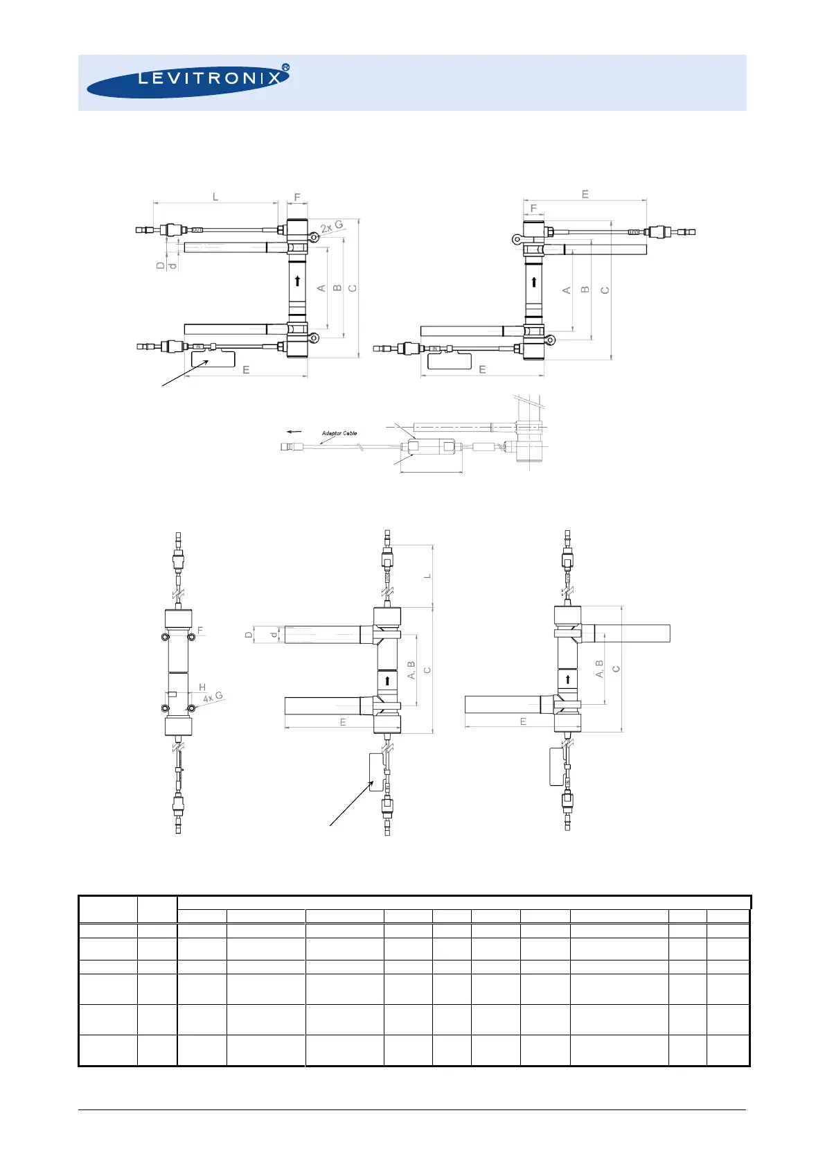
Figure 8: Dimension l
egend fo
r LFS-04 and LF
S-08 sensor
s
(left: U-shape, righ
t: Z-shape)
Figure 9: Dimension legend for flowsensors
LFS
-20, LFS-50 and LFS-80
(left: U-shape, righ
t: Z-shape)
Sensor
Type
Tube
Size
Dimensions in [mm]
A
B
C
D
d
E
F
G
H
L
LFS-
008
1/4"
80
±1
96
±1
134
±1
6.35
4.35
12
0
20
4
--
500
LFS-
04
(H)
3/8”
1/4"
80
±1
98.5 ±1 (99 ±1)
96
±1
136
±1
134
±1
9.53
6.35
6.33
4.35
12
0
20
4
--
500
LFS-
08
(H)
3/8”
80
±1
98.5 ±1 (100 ±1)
136
±1 (137 ±1)
9.53
6.33
12
0
20
4
--
500
LFS-
20
(H)
1/2"
80
±1
80
±1
136
±1
12.7
9.5
12
0
(117.7)
30
(
25.4)
M4
x 31 -> U-shape
M4
x 30 -> Z-shape
Max. Torque: 0.3 N
m
25
500
LFS-
50
(H)
3/4"
80
±1
80
±1
141.8 ±1
(
14
3.8 ±1)
19
15.8
13
0
(127.7)
30
(
25.4)
M5
x 31 -> U-shape
M5 x 30 -> Z-shape
Max. Torque: 0.5
Nm
30
500
LFS-
80
(H)
1”
80
±1
80
±1
148
±1
25.4
22.2
14
0
(137.7)
30
(
25.4)
M4
x 34 -> U-shape
M4 x 30 -> Z-shape
Max. Torque: 0.3 N
m
35
500
Table 9: Sensor dimensions
48
IN
T
o
Conver
ter
Female
Cover
Extensi
on Cab
le Concep
t
with IP-
65 Con
nector Prote
ction
Æ
12
Z-Shape
U-Shape
Tag with Calib
ration Data
Tag with Calib
ration Data
10
12
Table of Contents
Table of Contents
2
Safety Precautions
3
Specifications
4
Component Overview
4
Standard System Configurations
6
Single Channel Configuration - LFS-Series
6
Multi-Channel Configuration - LFS-Series
6
Specifications of Sensors
8
Specifications of Converters
9
General Specifications
9
Overview of Parameter Configuration
10
Basic Dimensions of Main Components
11
Dimensions of Sensors
11
Dimensions of Converters
12
Dimensions of Adaptor Cables
13
Installation
14
Installation of Converters LFC-1C and LFC-1C-F4
14
Overview and Preparation
14
Instructions for Electrical Installation
15
Configuration of Sensor Specific Data
15
Instructions for Mechanical Installation
16
Installation of Converters LFC-6C and LFC-6CIO
17
Overview and Preparation
17
Instructions for Electrical Installation
19
Configuration of Sensor Specific Data
19
Instructions for Mechanical Installation
20
Installation of Sensors
21
Overview and Preparation
21
Instructions for Electrical Installation
21
Instructions for Mechanical and Hydraulic Installation
22
Operation
23
General Timing Specifications
23
Startup Time
23
Thermal Stability Time
23
Zero Adjustment Activation Time
23
Automatic Zero Adjustment Duration
23
System Operation with LFC-1C / LFC-1C-F4
24
Standard Operation with PLC Interface
24
Typical Setups Using the PLC Interface
24
Operation with RS485
25
Standalone Operation with Display
25
Display Messages
26
System Operation with Converter LFC-6C and LFC-6CIO
27
Standard Operation with PLC Interface (LFC-6CIO Only)
27
Operation with RS485
27
Standalone Operation with Display
27
Display Messages
27
Operation with LEVIFLOW ® Configuration Software
27
Inspection and Maintenance
28
Troubleshooting
29
Common Troubles
29
Troubleshooting with LEVIFLOW Configuration Software
29
Technical Support
29
Appendix
30
Regulatory Status
30
CE Marking
30
Symbols and Signal Words
31
5
Based on 1 rating
Ask a question
Give review
Questions and Answers:
Need help?
Do you have a question about the Levitronix LEVIFLOW LFC-1C and is the answer not in the manual?
Ask a question
Levitronix LEVIFLOW LFC-1C Specifications
General
Brand
Levitronix
Model
LEVIFLOW LFC-1C
Category
Measuring Instruments
Language
English
Related product manuals
Levitronix LEVIFLOW LFS-SU
29 pages
Levitronix LEVIFLOW LFSC-i19X
19 pages
Levitronix LEVIFLOW LFSC-i16X
19 pages
Levitronix LEVIFLOW LFS Series
31 pages
Levitronix PuraLev i30SU
41 pages