4.3 System Operation with Converter LFC-6C and LFC-6CIO
4.3.1 Standard Operation with PLC Interface (LFC-6CIO only)
Table 12 for the analog outputs and Table 13 for the digital in/outputs shows the standard configuration of
the electrical interface (PLC). For other configurations the LEVIFLOW
®
configuration software has to be used
(according manual is Levitronix
Doc.# PL-4501-00). The hardware configuration is the same as for the PLC
of the LFC-1C. Therefore the same typical setup applies as described in Section 4.2.2.
4.3.2 Operation with RS485
Standard operation with LFC-6C is done with the RS485 interface, which also can be done with the LFC-
6CIO. The according MODBUS protocol can be requested at Levitronix
.
4.3.3 Standalone Operation with Display
The LFC-6C/LFC-6CIO can be used as standalone device, where the flow values can be read on the display.
The channel to be read can be chosen with the channel selection potentiometer on the display (see Figure
17d).
4.3.4 Display Messages
The 6-channel converter LFC-6C/LFC-6CIO displays basically the same messages as the single channel
converter LFC-1C / LFC-1C-F4 (see Table 14).
Additionally LFC-6C/LFC-6CIO shows on the display on the right side six LEDs (see Figure 17d). LEDs
indicate which channel has measurement error active (when channel selection is set to a specific channel 1-
6) or indicates, which flow is shown in display at the moment (when channel selection is set to 0).
4.4 Operation with LEVIFLOW
®
Configuration Software
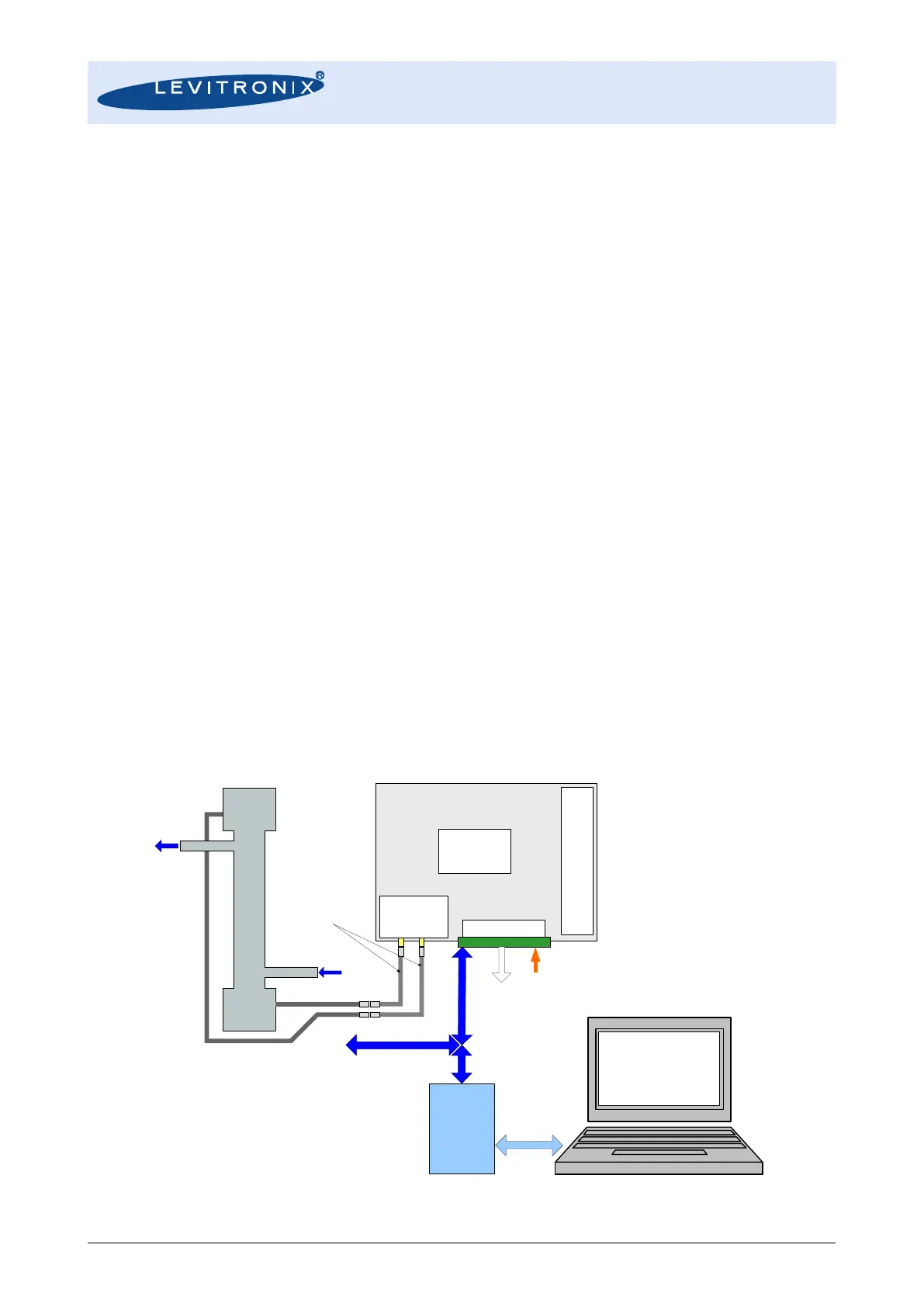
For debugging, data collection and configuration of the flowmeter system the LEVIFLOW
®
Configuration
Software is available at Levitronix
®
. Contact Levitronix
®
for a sample of the configuration software and the
according manual (Levitronix
Doc.# PL-4501-00). An approved USB to RS485 adaptor with the according
connection cable can be ordered according to the information in Table 3.
Note: The LFS-008 sensor with converter LFC-1C-F4 needs configuration software version V1.18 or higher.
The LFC-6CIO needs configuration software version V1.25 or higher
Figure 25: System operation with LEVIFLOW
®
configuration software