User Manual for LEVIFLOW
®
LFS Flowmeters
www.levitronix.com
PL-4502-00, Rev11, DCO# 18-107
3 Installation
3.1 Installation of Converters LFC-1C and LFC-1C-F4
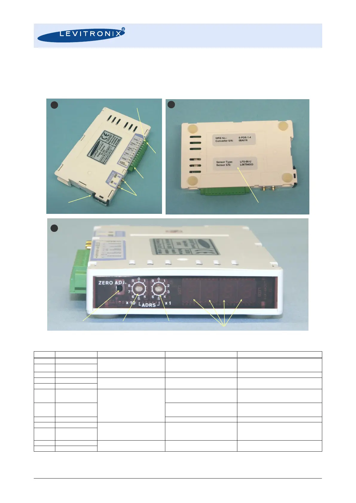
3.1.1 Overview and Preparation
Figure 15: Single channel converters LFC-1C / LFC-1C-F4
Voltage: 24 VDC ±10%
Current: 150 mA
Start Current: 4.4 A 2ms
See note in installation Section 3.1.2
4-20 mA or 0-20mA configurable
Load resistance < 600
Flow reading with 4-20 mA. Standard full
scale flow range of each sensor model.
Flow rate signal.
Update rate is 10ms.
Max. rating 30 V DC, 20 mA
Open collector
Configurable as Alarm High, Alarm
Low, Measurement Error, Volume
Counter Pulse, Volume Counter
Alarm, Flow as Frequency, Bubble
Detect
- Parameter: Flow Alarm High
- Setting: 105% of full scale
- Normally opened
Contact is made, when 105% of full scale flow
rate is exceeded.
- Parameter: Flow Alarm Low
- Setting: -5% of full scale
- Normally opened
Contact is made, when -5% of full scale flow rate
is reached.
Common Digital Out ground.
No-voltage contact or transistor open
collector
Is needed, if zero adjustment wants to be
triggered by PLC or when volume counter
function is used (integration of flow with volume
detection)
Digital communication in a sensor array.
or configuration with configuration SW.
Table 10: Standard configuration of interface connector (PLC) for LFC-1C and LFC-1C-F4