3.5 Hydraulic Circuit Design
Following general design rules help to operate the pump system optimally considering efficiency, optimum
priming behavior and low shear forces:
1. The general rule for minimum shear forces and optimum priming behavior is to minimize the pressure drop in the
inlet circuit and avoid negative pressure at the inlet of the pump head.
2. Minimize tubing length at the inlet of the pump head and maximize the ID (not lower than 1” is recommended).
This reduces the pressure drop and the tendency of cavitation.
3. Avoid any restrictions, valves, elbows, bended tubing and sharp edges at the inlet circuit of the pump head, which
potentially causes cavitation resulting in higher shear forces and bubble collection in the pump head with the
danger of priming loss.
4. Choose correctly aligned sealing rings and fitting adaptors to connect tubing to the in- and outlet of the pump
head. Consult the dimension drawings of the sealing ring and fitting adaptor manufacturer and check with the in-
and outlet dimensions shown in Figure 9. Miss-aligned sealing rings and fittings can be the cause of increased
shear forces and cavitation effects.
5. Place the pump at the lowest point of the hydraulic circuit. Optimum is as much as possible below a tank or
reservoir. This optimizes priming behavior and keeps the inlet pressure positive for low shear forces.
6. Keep the liquid level in the reservoir tank or bag as high as possible, which increases the inlet pressure of the
pump head and minimizes heat up of the liquid.
7. In general, the pump system placement and hydraulic circuit shall be designed that gas bubbles can leave the
pump housing and that the pump head remains primed.
8. To minimize heat up of the liquid the overall pressure drop in the hydraulic circuit shall be reduced as much as
possible.
9. It shall be avoided to pump longer times against a closed valve, which can cause heat-up of the liquid and higher
shear forces.
10. At higher liquid temperature the rules mentioned above become more important due to higher cavitation tendency
of the liquid.
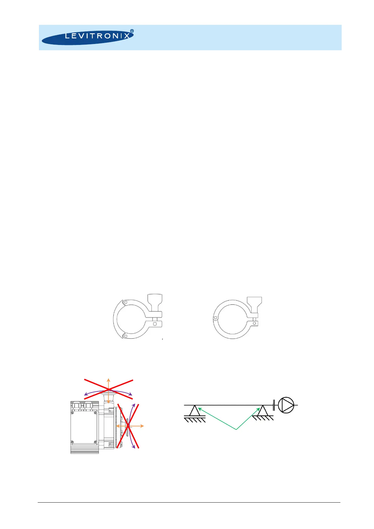
11. As the LPP-600.7/18 pump heads and the fittings are made out of plastics the usage of 3-part clamps instead of
2-part clamps (see Figure 22) for in- and outlet connection is recommended to prevent asymmetric stress during
high temperature treatments like SIP (steam in place) or autoclaving causing sealing and leakage issues.
Figure 22: 3-part clamps versus 2-parts
12. Load and stress at the inlet and outlet by heavy tubing and improper mounting alignment shall be avoided (see
Figure 23) as this can cause leakage issues due to distortion of the plastic pump housing.
Figure 23: Avoidance of stress forces and torques at the inlet and outlet of the pump head
Contact the Levitronix
®
Technical Service department (see Section 8) for more detailed considerations and
support on the design of the hydraulic circuit.
 Loading...