User Manual for PuraLev
®
600MU
www.levitronix.com
PL-4033-00, Rev09, DCO# 20-144
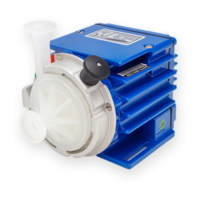
Figure 38: Screws of pump head (Stainless Steel INOX A4)
6.3.4 Insertion and Fixation of New Pump Head
Assure that on the new pump head the Fixation Disk is
not attached anymore. Then insert the pump head
smoothly into the motor. Rotate it until the pump head
holes and the motor threads are aligned.
6.3.5 Fixation of New Pump Head to Motor
Tighten the Screws M1 to M4 in the order as numbered in
Figure 38. Use sequences with incremental torque steps
in order to avoid fixing the pump head asymmetrically to
the motor.
Torque for LPP-600.7/18
(PVDF Hous.)
Torque for LPP-600.27
(SS Housing)
6.3.6 Start-Up and Functionality Check
Start up the system and check if the impeller is rotating
properly. If the pump is not operating as expected, make
sure that the metallic Fixation Disk or another magnetic
part has not accidentally attached itself to the bottom of
the pump head.
6.4 Re-Assembling of Pump Head
If possible, avoid disassembling the pump head. If this is
not avoidable, for example due to cleaning reasons, use
the following instructions to re-assemble a pump head.
6.4.1 Insertion of Impeller and Sealing
Insert the Impeller into the Housing Bottom and then
insert the Sealing into the relevant cavity (see Figure 36).
6.4.2 Press the Lid into the Housing Bottom
Press the Housing Lid in to the Housing Bottom. Do not
use the pump screws for doing this.
6.4.3 Tighten the Pump Head Screws
Tighten the pump head screws P1 to P8 in the order as
numbered in Figure 38. To avoid an asymmetric lid to
bottom alignment, use sequences with torque increments
until each screw is tightened according to the following
table:
Torque for LPP-600.7/18
(PVDF Hous.)
Torque for LPP-600.27
(SS Housing)
6.4.4 Final Assembly Check
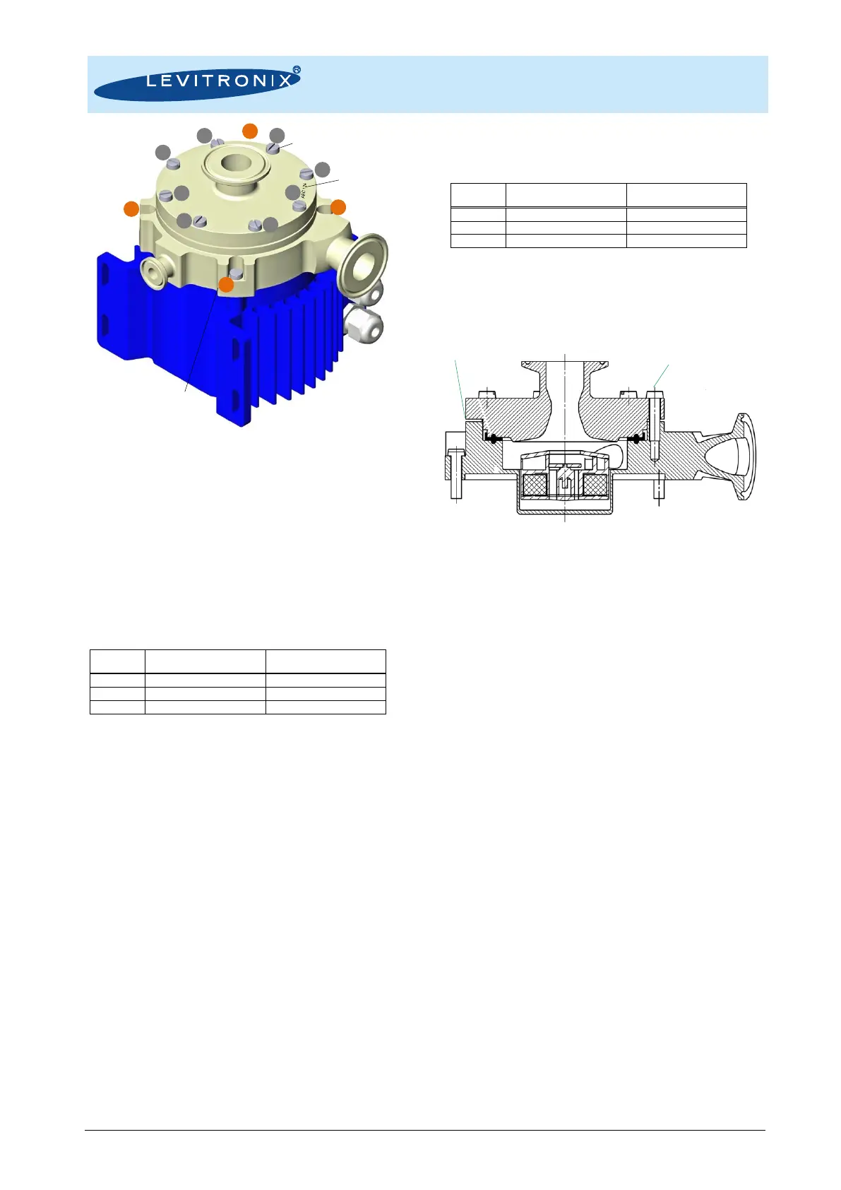
Check the uniformity of the gap between lid and bottom
and that all screws are tightened properly.
Figure 39: Cross-section of pump head with check points
6.5 Assembly into a Circuit
The following points shall be considered, when integrating
the pump head into a hydraulic circuit.
6.5.1 Usage of Fixation Disk
During handling, assembling and transportation of the
pump head with the hydraulic circuit it is recommended to
attach the Fixation Disk to the pump head bottom. This
fixes the impeller mechanically and reduces the magnetic
fields, which can attract other magnetic parts during
handling, sterilization and transportation.
6.5.2 Careful Handling of Multiple Pump Heads
Take care to the magnetic forces of the impellers when
handling multiple pump heads at the same time. Avoid
two pump heads coming together with force due to the
magnetic attraction, which might cause cracks.
6.5.3 Avoidance of Mechanical Stress
Do not apply too much bending forces to the fittings of the
pump heads LPP-600.7/18. It is recommended to use
3-way clamps (not 2-way) to attach stainless steel fittings.
This reduces the tendency to distort the PVDF fittings due
to different expansion coefficients of plastics and steel.
6.6 Maintenance
6.6.1 Check of Pump Head Screws
From time to time and specifically after heat treatments
like steam sterilization or autoclaving it is recommended
to check if the pump head screws still are screwed on
properly in order to assure proper of the pump housing.
6.6.2 Check of Sealing Property
The pump head design has recesses between lid and
bottom, which allow to seeing leakages immediately.
Regularly check these recesses for liquid leakage.
4x M6x25mm
(Screws M1-M4 for fixation of
pump head on motor)
8x M6x25mm for LPP-600.7/18
8x M6x12mm for LPP-600.27
(Screws P1-P8 for fixation of housing)
8x M6x25mm for LPP-600.7/18
8x M6x12mm for LPP-600.27
(Screws P1-P6 for fixation of housing)
Circular uniform gap of approximately
1.5 mm for pump heads LPP-600.7/18.
0.125-0.325 mm for pump head LPP-600.27.
 Loading...