User Manual 10H52188UM51 - Rev. 1 - 09/2011 21
Liebert NXC Single UPS Installation and Commissioning
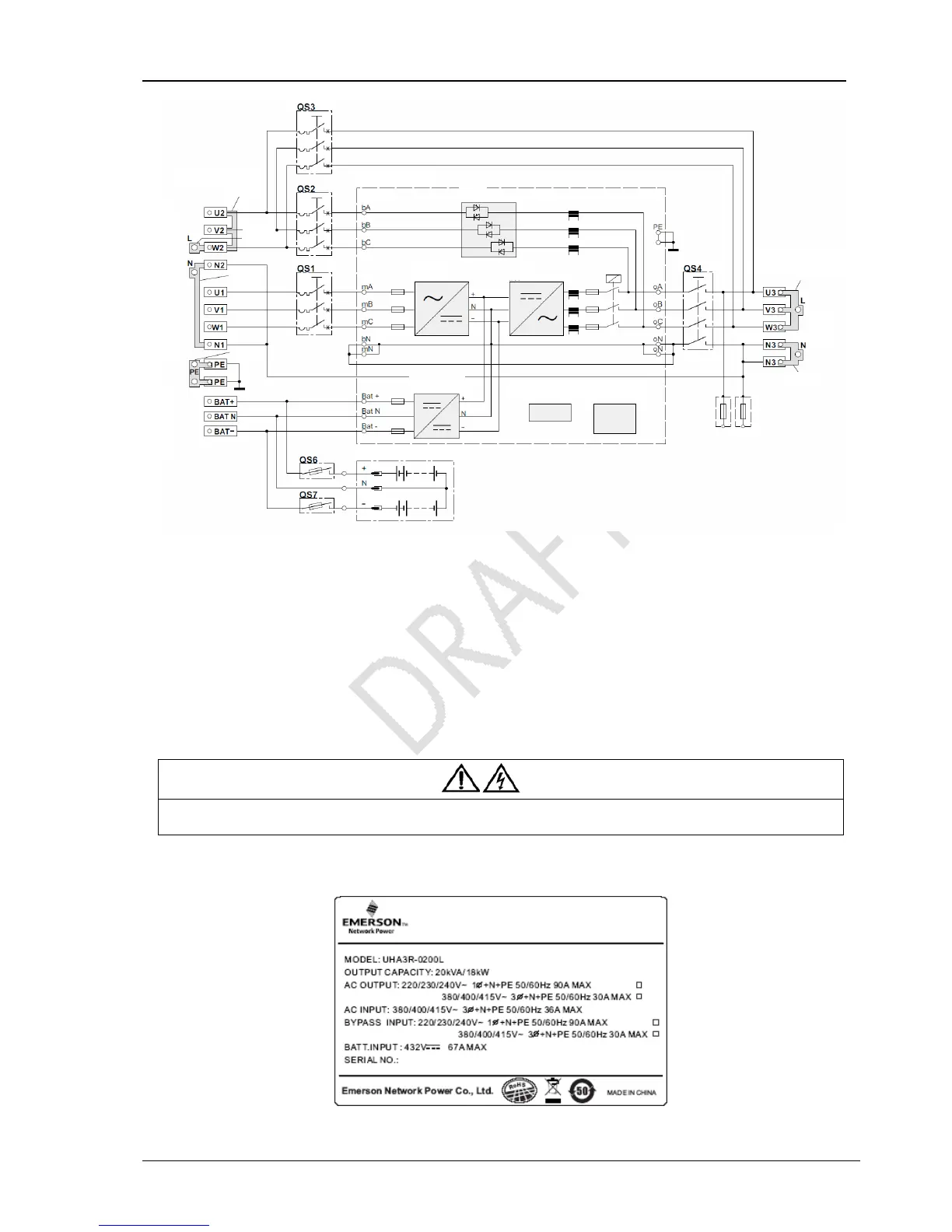
Figure 2-8 3-in 1-out, split-bypass configuration cable connection
4. Connect the live lines (input phase L1, L2 and input phase L3), N line and PE line respectively to the I/O terminal block (U1, V1
and W1 terminals) of the UPS, one screw hole of the copper shorting bar 4 with N1 and N2 terminals, and one screw hole of the
copper shorting bar 10.
5. Connect the copper shorting bar 8 to one end of the copper shorting bar 7 (see Figure 2-8), and connect the live line (bypass
input phase L) to the copper shorting bar 8.
6. Connect the bypass input N line to the copper shorting bar 4 with N1 and N2 terminals of the UPS I/O terminal block.
7. Connect the output L line, N line and PE line respectively to the copper shorting bar 5, copper shorting bar 4 with two N3
terminals, and the other screw hole of the copper shorting bar 10 of the UPS I/O terminal block.
Warning
Before the commissioning engineer arrival, if the load is not ready for accepting the power, please take good care of the safety
insulation located at the end of the output cable.
After the output cable connection, find the label shown in Figure 2-9 on the enclosure of the UPS and put a tick after “AC
OUTPUT” and “BYPASS INPUT” according to the actual situation for easy maintenance.
Figure 2-9 Label
Copper shorting bars
No. 7
UPS MODULE
INTERNAL BATTERY
RECT
INV
CHARGER
COMMUNICATION
PORTS
OP. AND DISP.
PANEL
OUTPUT
MAINS INPUT
EXT. BATTERY