User Manual 10H52188UM51 - Rev. 1 - 09/2011 7
Liebert NXC Product Introduction
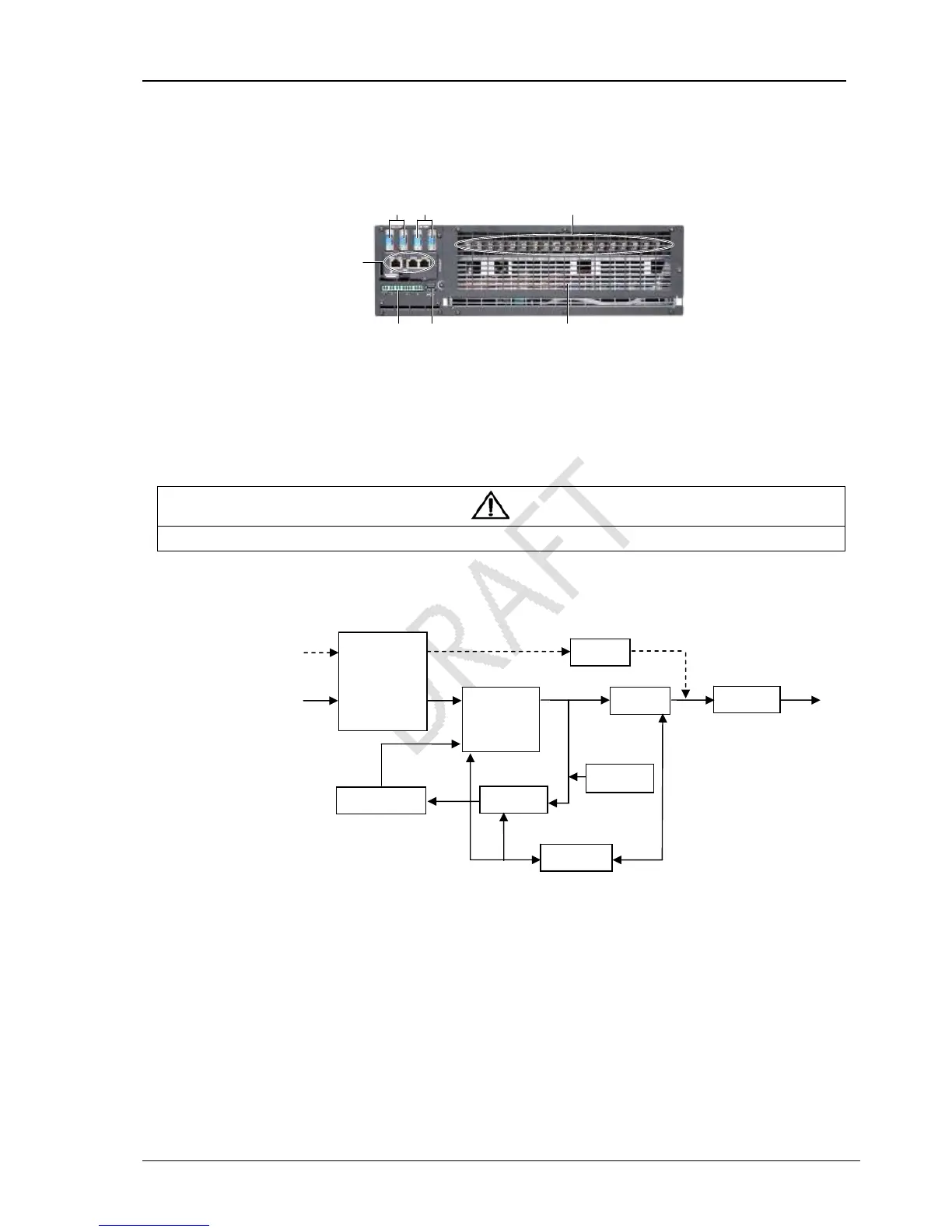
UPS module rear panel
As shown in Figure 1-3, the UPS module rear panel provides parallel ports, Load Bus Synchronization ports, terminal block,
Intellislot cards port, dry contact ports, USB port and ventilation holes. The SIC-SNMP card in the Intellislot cards port is optional,
it is sold separately.
Figure 1-3 UPS module rear panel
Figure 1-4 show the location of user I/O connectors
Figure 1-5
Note
Non-authorized personnel are prohibited from opening the UPS chassis cover.
1.4 Operating Principle
The operating principle of the UPS is shown in Figure 1-6.
Figure 1-6 UPS operating principle
1. The UPS is composed of mains input (mains and bypass), I/O filter, rectifier/PFC, charger, inverter, bypass, battery, DSP
controller, System Control Power and UPS output.
2. When the mains is normal, the rectifier will start, and the charger will charge the battery string. Before turning on the UPS,
the output voltage is the bypass voltage, and the mains supplies power to the load through the bypass. After turning on the UPS,
the inverter output is connected to the load, and the mains supplies DC power to the inverter through the rectifier/PFC circuit.
The inverter then converts DC power into pure sine wave AC power, and supplies AC power to the load through the electronic
transfer switch.
3. When the mains is abnormal, the rectifier/PFC circuit boosts the battery voltage and supplies it to the inverter. The inverter
then converts it into pure sine wave AC power, and supplies AC power to the load through the electronic transfer switch.
4. After the mains returns to normal state, the UPS will automatically transfer from battery mode to Normal mode, the mains
supplies DC power to the inverter through the rectifier/PFC circuit, and then the electronic transfer switch supplies DC power to
the load.
Input filter
Bypass
Inverter
Output filter
Rectifier/PFC
Auxiliary