User Manual 10H52188UM51 - Rev. 1 - 09/2011 33
Liebert NXC Parallel UPS Installation and Commissioning
Table 3-2 Parallel parameters setting
Parameters Default value Parallel parameters setting
Single Group Batt Cap 0014 Set the parameter according to the actual battery capicitity
Battery Cells Number 32 Set the parameter according to the actual battery number
Equalize Charge Allowed Enabled Set the parameter according to the actual battery charicteristic
Shared Battery Disabled
Select “Enabled” if there is shared battery, select “Disabled” if there is no shared
battery
System Configuration Single Parallel
Parallel requisite units 1 Set the paramerter to “3” if there are four UPSs to form 3 + 1 parallel system
Parallel Redundant Units 0 Set the paramerter to “1” if there are four UPSs to form 3 + 1 parallel system
ECO Mode Normal Normal
Output frencency level 50Hz Set the parameter according to the actual power grid, 50Hz/60Hz can be selected
Output voltage level 400V
Set the parameter according to the actual power grid, 380V/400V/415V can be
selected
3 Phase Output or 1 Phase
Output
Three Select “Three” when is 3 Phase Output, select ”Single” when is 1 Phase Output
Note: output frequency level and output voltage level will be active after power-off, but will not be displayed on LCD panel, the
settings will be valid after manual power-off.
The default values of other parameters are listed in Table 2-5.
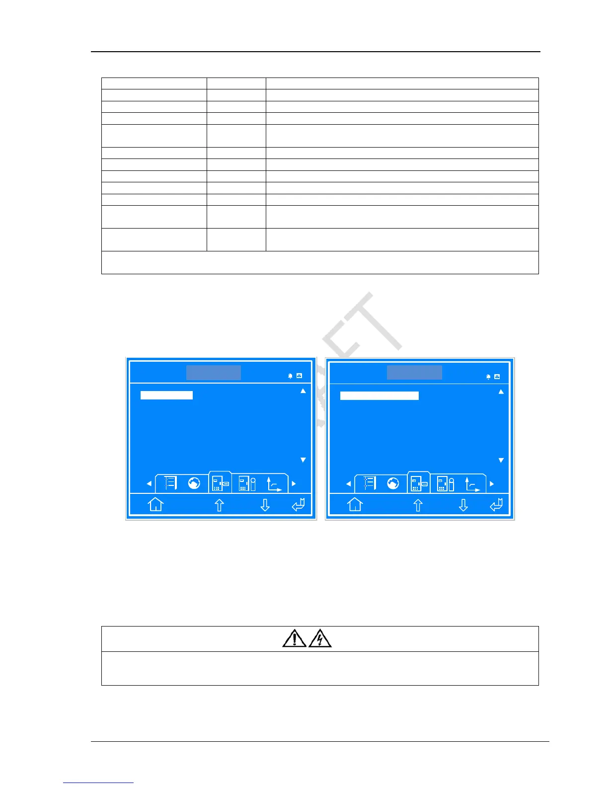
For the parallel system with N + X (2 ≤ N + X ≤ 4), set ‘System Configuration’ to ‘Parallel’, ‘Parallel requisite units’ to ‘N’ (1 ≤ N ≤
4), ‘Parallel Redundant Units’ to ‘X’ (0 ≤ X ≤ 3). Take the 3 + 1 parallel system for example, set ‘System Configuration’ to ‘Parallel’,
‘Parallel requisite units’ to ‘3’, ‘Parallel Redundant Units’ to ‘1’, as shown in Figure 3-7.
ITA 016 kVA
Settings
Unit 1#
Enabled Disabled
System Configuration Parallel
Parallel requisite units 3
ESC
Disabled
Shared Battery
1 2 3 4
Single Parallel
14:30:36
ITA 016kVA
Settings
Unit 1#
0 1 2 3
ECO Mode Normal
Output frequency Level 50Hz
ESC
1
Parallel Redundant Units
Normal ECO
50Hz 60Hz
14:30:36
Figure 3-7 Settings interface
3.4.3 Power-On Commissioning For Parallel System
Power on and commission each UPS of the parallel system respectively, namely power on one UPS each time, and other UPSs
are in the close status, the specific commissioning procedures are as follows:
1) Close the external output MCB and input MCB of one UPS, the UPS is powered on. Ensure that other UPSs MCBs are closed.
Close the corresponding internal input Output Circuit Breaker, bypass LBS and output LBS of the UPS.
Warning
After closing the UPS external output MCB and UPS internal output LBS, the UPS output terminal block, the distribution output
terminals and load will be live, pay attention to the personnal safety to avoid electric shock. Note whether it is safe to feed power to
load.
2) LCD displays the self-test screen; the fault indicator (red) and inverter indicator (green) are on at the same time for about 5
seconds. After the self-test, UPS enter the bypass mode, the fault indicator turns on and the buzzer beeps for 1 second.