User Manual 10H52188UM51 - Rev. 1 - 09/2011 29
Liebert NXC Parallel UPS Installation and Commissioning
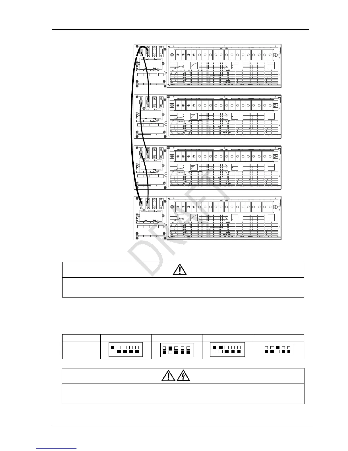
UPS 1
bCmCbBmBbAmAbNmNoN oN oA oB oC
PE PE
UPS 2
bCmCbBmBbAmAbNmNoN oN oA oB oC
PE PE
UPS 3
bCmCbBmBbAmAbNmNoN oN oA oB oC
PE PE
UPS 4
bCmCbBmBbAmAbNmNoN oN oA oB oC
PE PE
DB9 male port
DB9 female port
Figure 3-2 Cable connection schematic diagram of 3 + 1 parallel system
Note
1. The Emerson parallel cables must be used for the parallel system.
2. The parallel communication fault occurs when carrying out the parallel commissioning, check whether the connection of the
parallel cables is correct, and whenther the pin1~ pin9 are connected.
Setting parallel addresses
The parallel addresses for all UPSs in parallel system should be set. The parallel addresses can be set through the DIP switch on
the UPS front panel (see Figure 1-2). Remove the DIP switch cover, and set the DIP switch according to Table 3-1.
Table 3-1 DIP switch settings
Parallel addresses Parallel 1# Parallel 2# Parallel 3# Parallel 4#
DIP switch
position
ON
12345OFF
ON
12345OFF
ON
1 2345OFF
ON
12345OFF
Warning
1. The default setting for DIP switch is ‘1’. However, you should set the DIP switch position for the parallel system according to the
description listed in Table 3-1. Otherwise, the UPS fault will occur.
2. The parallel address must be unique for each UPS unit.
DB9 male port
DB9 female port
UPS 1
UPS 2
UPS 3
UPS 4