User Manual 10H52188UM51 - Rev. 1 - 09/2011 31
Liebert NXC Parallel UPS Installation and Commissioning
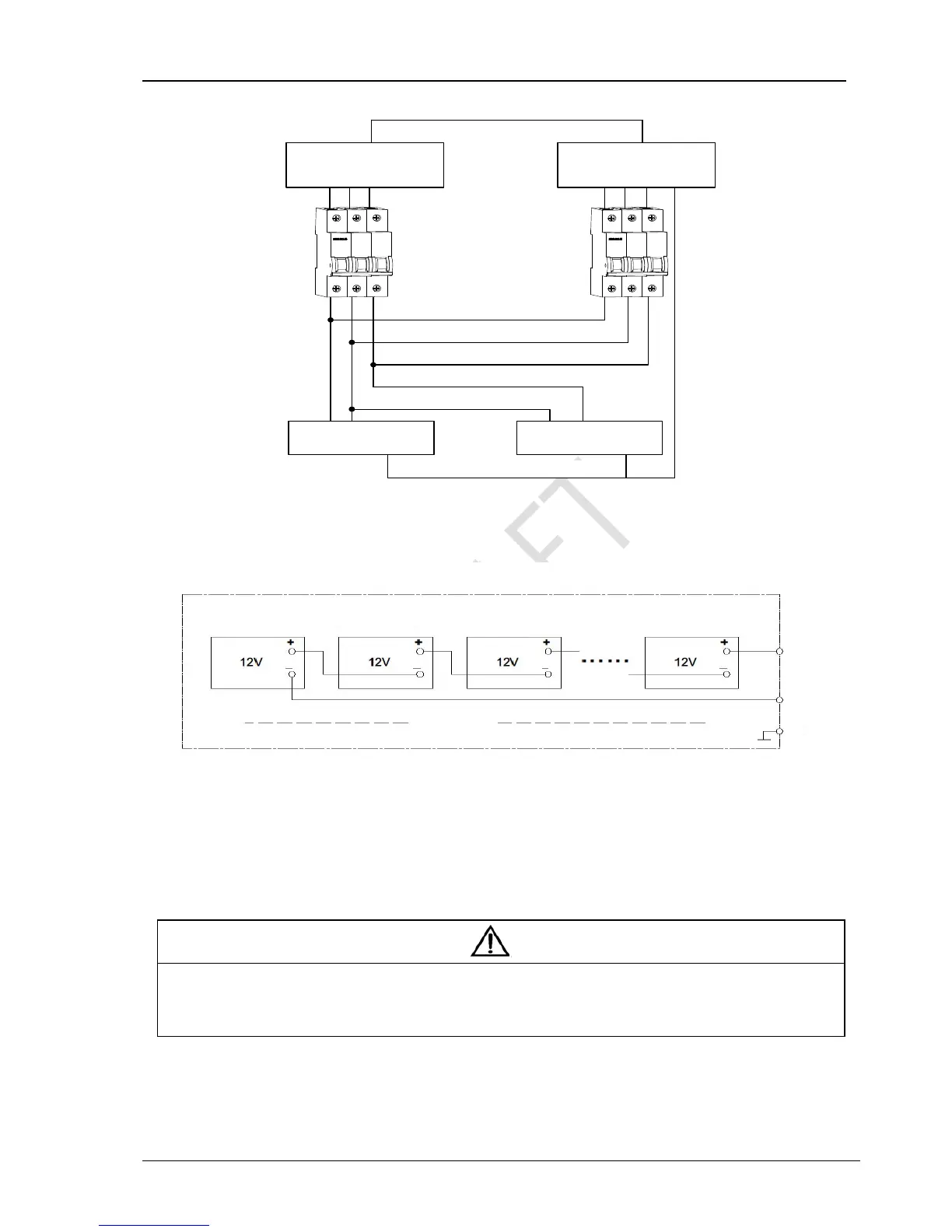
PE
UPS 1 UPS 2
UPS 1 MCB
UPS 2 MCB
+- PE
Positive battery
string
+- PE
Bat+ Bat N Bat- Bat+ Bat N Bat- PE
Negative battery string
Figure 3-4 Connection diagram of shared battery string in 1 + 1 parallel system
Refer to Figure 3-5 to configure the positive battery string and negative battery string
Figure 3-5 Internal connection diagram for positive battery string and negative battery string
2. Setting
Power on the system, set each single UPS to shared battery string configuration through the LCD menu ‘Settings’ -> ‘Shared
Battery’ from each UPS unit; set the LCD menu ‘Settings’ -> ‘Battery Cells Number’ and ‘Single Group Batt Cap’ from each UPS
unit, and each UPS unit setting must be the same, as shown in Figure 3-6.
Note
1. For the parallel system used the shared battery strings, make sure that the LCD settings are correct. Refer to 3.4.2 for details of the
settings.
2. For the parallel system used the shared battery strings, the ‘Single Group Batt Cap’ on the LCD setting of each UPS stands for the total
capacity of battery strings, and each UPS can calculate the battery capacity itself automatically.
UPS 1
UPS 1 MCB
UPS 2 MCB
UPS 2
Bat+ Bat N Bat- PE Bat+ Bat N Bat- PE
Positive battery
string
Negative battery string
first Block
second Block
third Block
sixteen Block
Battery string
Bat+
Bat-
PE
Battery cabinet