7. Function description
The lift is a so-called “dead man’s switch” lift, i.e., the push buttons must be pushed in
throughout the entire operation.
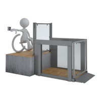
The lift is easy to operate: The user summons the lift using one of the buttons on the wall, on
the call station column or the accompanying remote control (optional equipment). When the
user is on the platform, it is operated from the panel on the side, from where transport to the
upper or lower level is selected.
8. Assembly
The lift is installed by an authorised service technician. Do not attempt to move or uninstall the
FlexStep or to repair it. This MUST be done by an authorised service technician.
In the event of incorrect assembly, there may be a safety risk for users. Liftup is exempt from
any liability if assembly and installation are not performed by an authorised service technician.
Contact your dealer for further information regarding installation of the lift:
https://www.liftup.dk/us/distributors/
9. Start-up
The FlexStep must always be connected to a 100-240 V socket and be switched on. Normally,
the FlexStep is always in “standby mode”, i.e., it is ready for use as soon as one of the operation
keys is pressed.
If the emergency stop button is pressed, or the lift has been disconnected through the key
switch, this must be deactivated before the lift can be used (find out more in section 10).