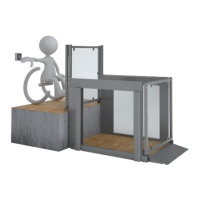
The device described in this manual is the EasyLift, a lifting platform designed to transfer wheelchair users or disabled people between two levels, with a maximum travel height of 1250 mm. The manual refers to the EasyLift as a "lifting platform," or simply "lift." The device aims to provide "equal opportunities" by developing "dignified aids, not machines," emphasizing aesthetics, design, and safety.
Function Description:
The EasyLift is a lifting platform that can be supplied with doors or automatic ramp/roll-off protection. For the EasyLift 1100 model, it can also be equipped with a Vertical Safety Barrier and doors with locks for indoor use. The lift is designed to move between two levels, facilitating accessibility. The operation involves a control unit, which includes a power supply, control boards, jumpers, LED signals, and dipswitches. Call stations, which can be standard wired, key-operated, or wireless (wall-mounted or handheld remote), are used to operate the lift. The lift also features an ON/OFF switch and an Auto Return Function. Safety features include pressure plates, micro switches for pressure plates, and audible alarms.
Important Technical Specifications:
- Travel Height: Maximum 1250 mm.
- Power Supply: The control unit consists of a power supply unit (103080) and a PCB for connection box (102726). Both are mounted on the bottom rail. Two control boxes (103482) are mounted on each side of the lift.
- Battery: The lift is equipped with batteries. Even if the power supply is not connected, the lift can move.
- Electrical Protection: The power supply converts from mains to the charger and is housed in an IP 67 enclosure, equipped with a Class II transformer using double reinforced insulation. This transformer does not normally have to be equipped with a protective earth connection. The remaining Low Voltage power circuits are housed inside the metal structure of the lift.
- PELV (Protective Extra-Low Voltage): All circuits on the lift are supplied from 24 Volts batteries and converted by SMPS's fulfilling PELV. The lift, including the metal structure, depends on national safety regulations to be connected permanently to the protective earthing system with a minimum 1BAWG / 0.75mm² wire.
- Wall Profiles: The wall profiles need to be fitted to the adjoining wall to ensure a stable performance. The length of the wall profiles must be elevation height +1100 mm, and there should always be 10 mm of clearance in the bottom between the wall profiles and the floor.
- Door Actuator Clearance: For door actuators attached on the left-hand side, there should be a clearance of 10 mm between the floor and profile.
- Pull Force for Mounting Screws: Screws attaching the lift to the building must withstand a Pull Force of not less than 0.5 kN each. If the strength of the screw attachment is validated by test, the minimum withdrawal strength is 1.5 kN, with a Factor of Safety > 3. A minimum of 3 screws are required in each Vertical Rail Guide.
- Platform Height Setting: The 1st programmable height setting (Platform Lifting Height) is the position where the platform will stop when it reaches the top landing. The platform height can be adjusted to approximately 70 mm thick.
Usage Features:
- Control Buttons: Buttons for "lift up," "lift down," and "calibrate the system" are available. An emergency stop button is also present.
- LED Signals: Various LED signals indicate the status of the lift, such as Key locked, Button activated, Remote control activated, Power supply connected (mains), and different states for upper/lower gates, IR stairs, and IR platform.
- Call Stations:
- Standard Wired Call Stations: Connections for Lower Call Station (Green/Common, Brown/Up, White/Down) and Upper Call Station (Green/Common, Brown/Up).
- Key Operated Call Stations: Similar connections to standard wired, with an added key switch for operation.
- Wireless Call Stations (Wall Mounted/Handheld): These stations need to be paired with the receiver. The pairing process involves setting a dip switch to ON, pressing the emergency stop, and then switching the ON/OFF switch. The control LED on the call station will flash rapidly when paired.
- ON/OFF Switch: The lift is fitted with an ON/OFF switch, located on the right-hand side of the main control. This button is used to disconnect the power supply to the lift. If the user switches this off at the same time as activating the emergency stop, the lift will be completely powered off.
- Auto Return Function: The lift will return to a previous position if the emergency button is released after moving the lift.
- Calibration: The lift will lose its position if it is moved manually. Call station/onboard buttons will make the lift go down to the lower position. During this movement, some actuators can be faster than others, leading to arrival at a lower position, which is normal. All four actuators are "at zero" (see picture below taken from Liftup Service Tool) all four actuators will show a green light and a "0" at Position. Once this is done, the lift can move normally again.
- Audible Alarms: If "speak" is installed, alarms will be activated in case of an overload, battery fault, under pan switch activation, or emergency stop. Otherwise, an alarm tone will sound.
Maintenance Features:
- Unpacking and Moving: After opening the wooden or carton pallet, all packaging around the lift needs to be removed. The lift is equipped with batteries, allowing it to move even if the power supply is not connected. To move the lift, changes to the safety circuit of the product are required, which are delivered by default with all safety functions active. The cover for the control box needs to be removed to access the primary control board. Jumpers (Upper Gate SW, Under Pan SW) need to be moved to move the product. Releasing the emergency button will show all green LEDs. The UP button on the platform moves the product upwards. A fork lift can be used to remove the lift from the wooden pallet.
- Actuator Replacement: This involves dismounting the actuator by pushing the "lift down" button until the platform is positioned at lower landing, pressing the emergency stop button, removing the top cover, disconnecting the cable, unscrewing the four screws holding the actuator, and then mounting the new actuator in reverse order.
- Spindle Unit Replacement: This involves unscrewing four screws and removing the foot plate under the actuator, then unscrewing three screws holding the spindle unit. The outer actuator tube is released from the extension pipe using flat pliers to bend the sheet metal lock. The middle actuator tube is released from the top bracket on the spindle unit using a small screw driver. The spindle unit is pulled out from the outer actuator tube. The new spindle unit is inserted and mounted in reverse order, ensuring wires are not damaged.
- Automatic Ramp/Roll-off Protection Maintenance: This involves removing the black plastic cover by unscrewing two screws, gently removing the ramp tube, and disconnecting the wires. The brass bracket is pulled out from the ramp tube, and the lock pawl is released. The screw holding the motor and lock assembly is unscrewed. The motor and lock assembly are gently pulled out from the ramp tube, using a M5 screw to retract it. The motor is pushed in using a long M5 screw, ensuring the cable is not squeezed. The lock assembly is assembled, and the lock pawl is fastened to the side frame. The micro switch is adjusted to activate when the lock pawl is out and not activate when the lock pawl is in the pipe.
- Unlocking Door in Emergency: In case of emergency/malfunction, the folding spring bolt needs to be released. This involves pulling out the spring bolt from the shaft of the clevis using a suitable tool, attacking the lower side, and releasing the spring. If the door is equipped with an automatic door lock, it can be unlocked with a triangular key (automatic door lock only available on EasyLift 1100 doors). Once the fault is corrected, the door can be connected again in reverse order.
- Service Mode: The system can be set into service mode to adjust the lift to the lower level, push the "up" button on call stations, record the new lifting height, and push the emergency button. Features in service mode can be calibrated or not calibrated.
- Safety Pressure Plate Adjustment: The micro switches are adjusted by loosening two screws underneath the frame of the lift, moving the micro switch gently forwards or backwards, and tightening the screws. The switch is tested by activating the pressure plate while maneuvering the lift down.