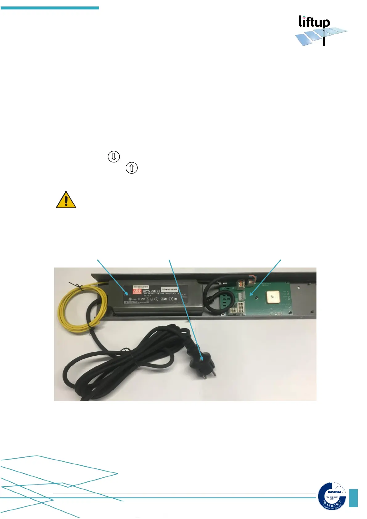
3. Control unit
The control unit consists of the power supply unit (103080), the PCB for connection box
(102726), both factory mounted on the bottom rail under the lift and two control boards
(103482) mounted inside the two control boxes, placed on each side of the lift.
During installation is not necessary to have the power supply unit (PSU) connected to mains;
the lift is able to run on the battery pack alone. It will give alarm until the PSU-charger is
reconnected.
Make sure to place any jumpers to make it run – see section 5.3.
- Release the emergency stop button.
- Using the button on the lift, now push “lift down”, and calibrate the system.
- Now push the button to move the lift to the upper level.
ATTENTION! Remember to push the emergency stop button, before you start
working underneath the lift.