DVI-TP-TX200/TX300/RX100
User’s Manual Rev. 1.0
Page 13 / 29
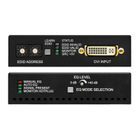
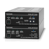
2.9. Front and rear view
2.9.1. Front view of DVI-TP-TX200/TX300
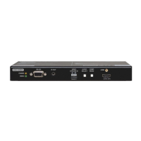
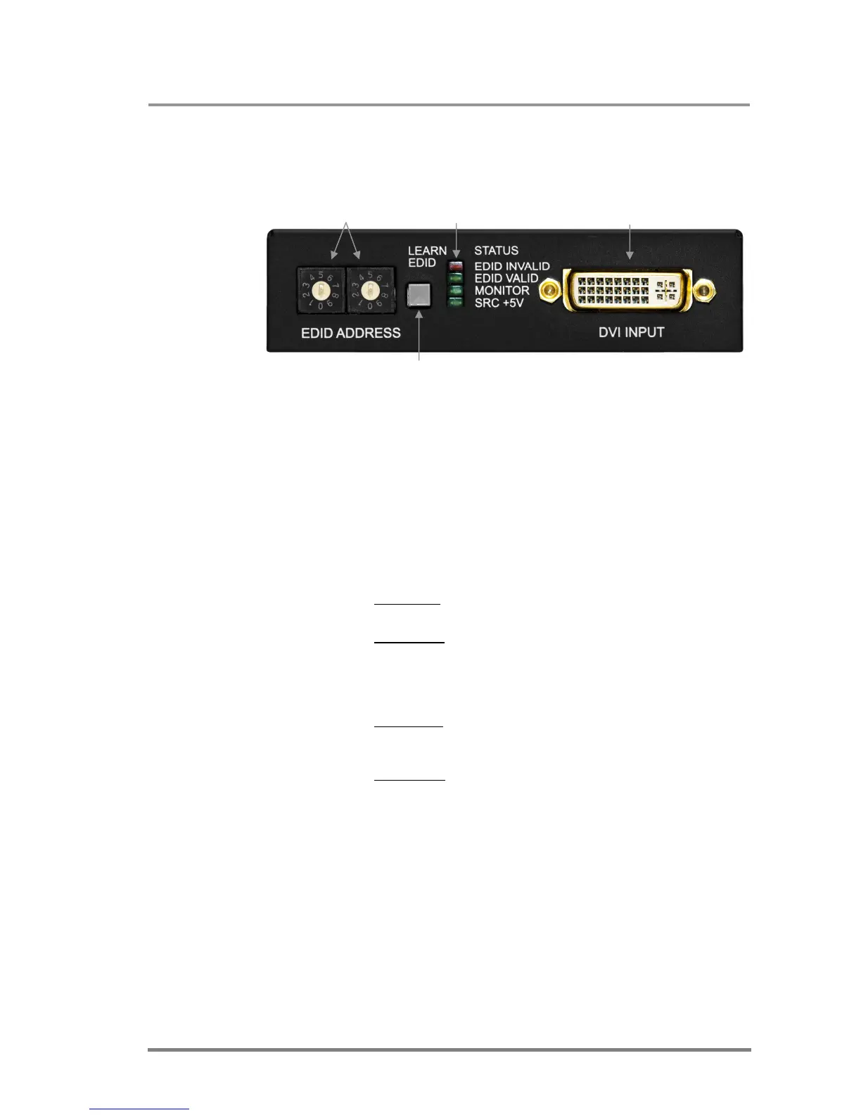
Address selection Status LEDs DVI Input connector
Learn EDID button
EDID Address The rotary switches select one of 100 addresses. Addresses
1…50 are factory preset and 51…99 are user programmable.
Address 00 enables transparent mode. For more information,
see chapter 3.3. Use a flat head screwdriver that fits into the
actuator. Avoid the use of keys, coins, knives and other sharp
objects because they might cause permanent damage to the
rotary switches.
Learn EDID button Stores the EDID of the display device attached to MONITOR
OUTPUT in the selected memory address between 51…99. To
learn the EDID, select an appropriate address with the rotary
switches and press and hold the Learn button for two seconds.
EDID status LEDs Function 1: display the firmware version of the device. For more
information, see chapter 3.1.
Function 2: after applying a Hot Plug signal to MONITOR
OUTPUT, these LEDs indicate that the unit is reading the EDID
from the connected display device. If the green LED is blinking
then the EDID is valid, if the red LED is blinking, then the EDID
is invalid or missing.
Function 3: (main function) these LEDs indicate whether the
selected EDID is valid (solid green = valid, solid red = invalid or
empty memory selected).
Function 4: after pressing the LEARN button, these LEDs
indicate whether the learn process was successful (green
blinking = successful, red blinking = unsuccessful). For more
information, see chapter 3.2.
Monitor LED Indicates if a display device (or matrix switcher, repeater, etc.)
is connected to the MONITOR OUTPUT connector and sends a
valid Hot Plug Signal on Pin 16 through the DVI cable.
SRC +5V LED Indicates if a DVI source is connected to the DVI-TP-
TX200/TX300, it is powered on and sends +5V signal to Pin 14
of the input DVI connector.
DVI Input Connect one DVI-D or DVI-I cable (only digital pins are
connected internally) between the DVI source and DVI-TP-
TX200/TX300.