DVI-TP-TX200/TX300/RX100
User’s Manual Rev. 1.0
Page 17 / 29
2.10. Electrical connections
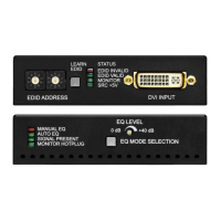
2.10.1. DVI inputs and outputs
DVI-TP-TX200/TX300 and DVI-TP-RX100 provide 29 pole „digital only” DVI-I
connectors for input and output connections. Always use high quality DVI cable for
connecting sources and displays.
Pin Signal Pin Signal Pin Signal
1
TMDS Data2-
11
TMDS D1/3 Shield
21
TMDS Data5+ (nc)
2
TMDS Data2+
12
TMDS Data3- (nc)
22
TMDS Clk Shield
3
TMDS D2/4 Shield
13
TMDS Data3+ (nc)
23
TMDS Clock+
4
TMDS Data4- (nc)
14
+5V Power
24
TMDS Clock-
5
TMDS Data4+ (nc)
15
GND (for +5V)
25
R (not connected)
6
DDC Clock
16
Hot Plug Detect
26
G (not connected)
7
DDC Data
17
TMDS Data0-
27
B (not connected)
8
VSYNC (nc)
18
TMDS Data0+
28
HSYNC (nc)
9
TMDS Data1-
19
TMDS D0/5 Shield
29
Analog GND
10
TMDS Data1+
20
TMDS Data5- (nc)
Table 1. Single link DVI-I “digital only” connector pin assignment
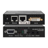
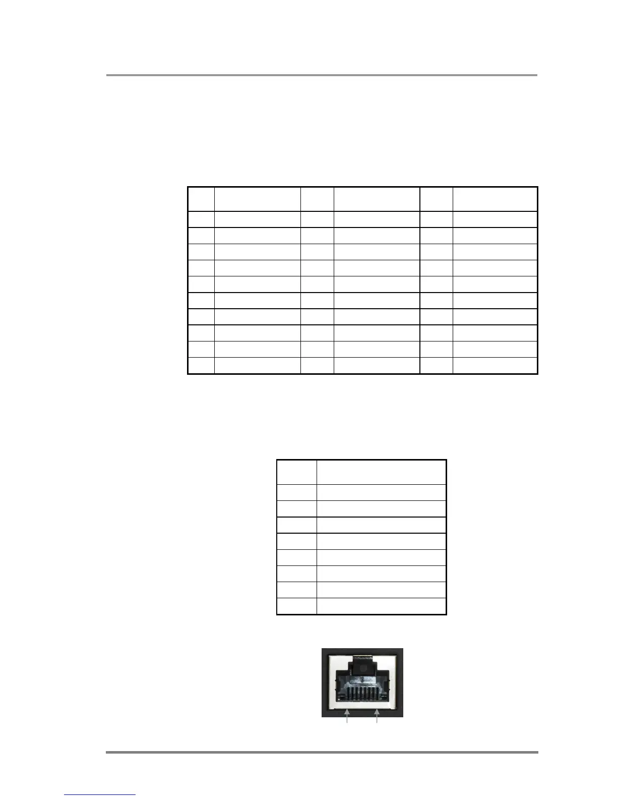
2.10.2. CATx inputs and outputs
DVI-TP-TX200/TX300 and DVI-TP-RX100 are equipped with shielded CAT6 RJ45
connectors.
Pin Signal CATx
1
TMDS Data0+
2
TMDS Data0-
3
TMDS Clock+
4
TMDS Data1+
5
TMDS Data1-
6
TMDS Clock-
7
TMDS Data2+
8
TMDS Data2-
Table 2. RJ45 connector pin assignment
Pin 8 Pin 1