LMAIM1501 LY Installation and Maintenance for LY 1001, LY 2001 and LY 3001 5-1
5 Installation Instructions
5.1 Safety Precautions
a WARNING: Read this Installation and Maintenance Manual carefully and completely before attempting to
install, operate, or troubleshoot the Limitorque LY actuator.
5.2 Initial Actuator Preparation
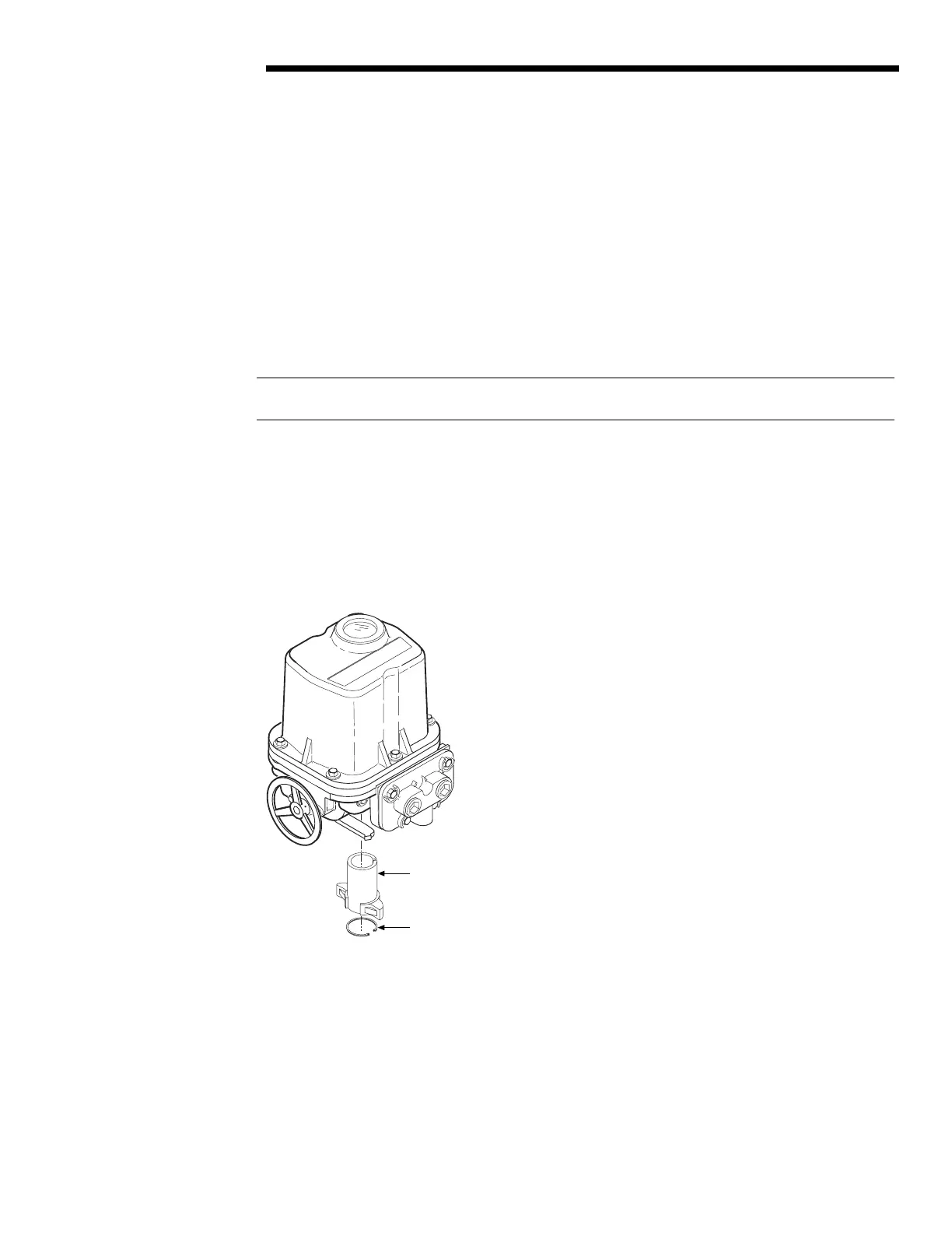
Piece numbers refer to Figure 5.1.
1. Remove the Retaining Drive Ring (piece #165 or #109) and Torque Nut (piece #32) from actuator.
Figure 5.1 – Torque Nut and Retaining Drive Ring Removal from an LY 1001
2. If Torque Nut has been bored and keywayed by Limitorque, verify dimensions and keyway location for proper
compatibility with the valve stem.
3. If Torque Nut has not been bored and keywayed by Limitorque, it is provided solid (blank) to allow customer
to custom key and bore up to the maximum permissible sizes as listed in Table 5.1.
L imitorq u e
#32 Torque Nut
#165 (LY 1001)
#109 (LY 2001/3001)
Torque Nut Retaining Drive Ring
Flow Control Division
Limitorque Actuation Systems