LMAIM1501 LY Installation and Maintenance for LY 1001, LY 2001 and LY 3001 5-9
5.7.2 Setting the OPEN Limit Switch
NOTE: When setting the OPEN Limit Switch, be careful not to rotate the CLOSE Limit Cam; rotating it will change
the adjustments you previously made on the CLOSE Limit Switch.
1. Put the actuator into MANUAL operation by moving the Declutch Lever in the direction of the arrow on the
lever until the Declutch Lever locks in place. If Declutch Lever is difficult to move, see Section 6.4, Manual
Operation for instructions to release the Declutch Lever.
2. Turn the Handwheel to move the valve to the full OPEN position.
NOTE: Most applications require turning the Handwheel CCW to obtain the full OPEN position. The Drive
Sleeve and Limit Cams also rotate in CCW rotation to the OPEN position. If your application is configured
differently, keep in mind the descriptions in this manual will describe rotation directions opposite of your
application.
3. Loosen Setting Nut (piece #7-10) located at the top of the switch bracket. (See Figure 5.7.)
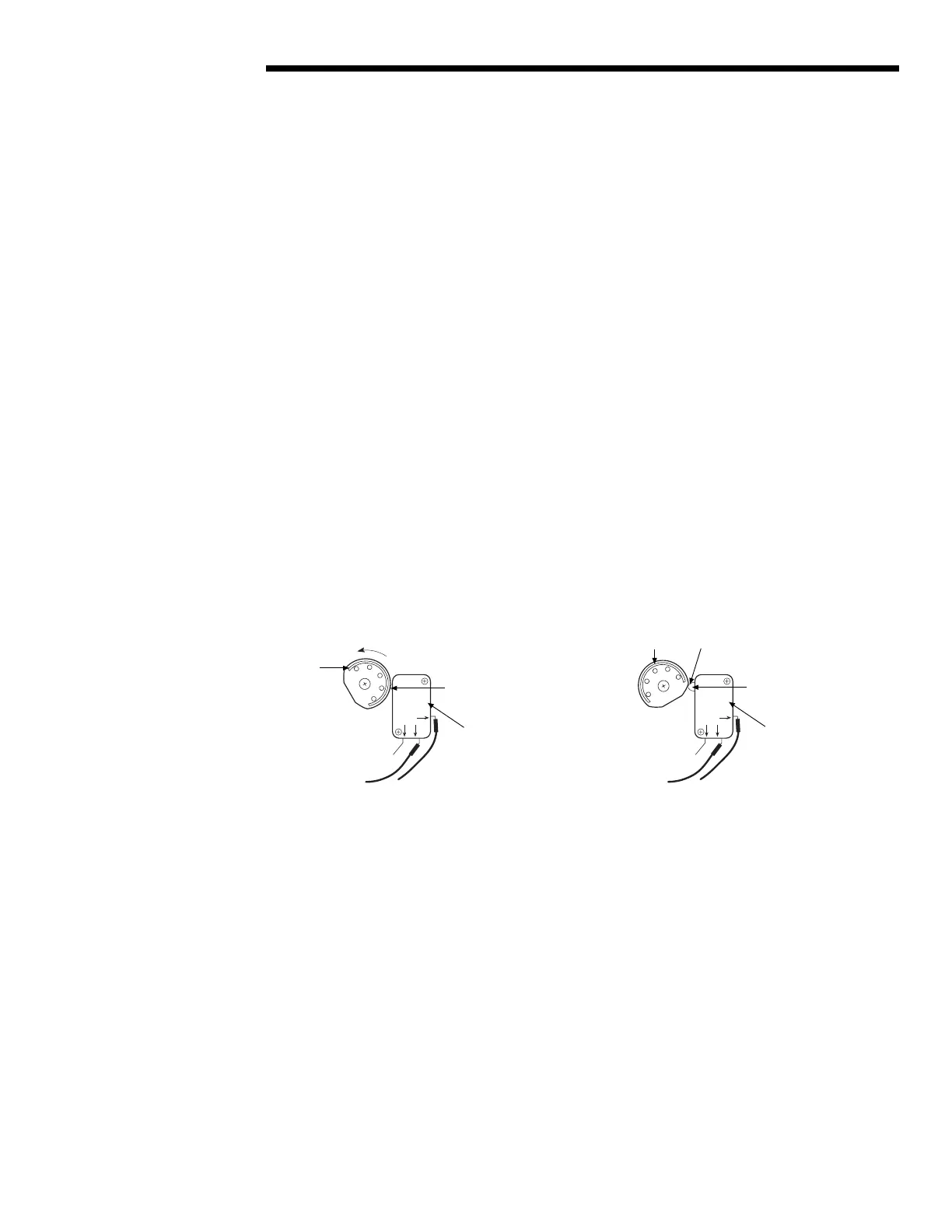
4. Rotate the OPEN Limit Cam CCW through the high side to the trip point until the Switch Plunger is released.
This causes the N.O. contact to open. There will be no electrical continuity at the trip point when measuring
with an ohmmeter between the common lead and the N.O. lead; you may also hear a faint “click” at the trip
point.
NOTE: During actuator operation, when the Switch Plunger trips, the N.O. contact is released, causing the
Limit Switch to stop the actuator in the OPEN position.
Figure 5.9 – Setting OPEN Limit Cam
5. Retighten Setting Nut (piece #7-10).
NO
NC
COM
NO
NC
COM
High Side
Rotate CCW to reach
OPEN Trip Point
Switch Plunger
OPEN Limit Cam
OPEN microswitch
position while valve
is traveling from CLOSED
toward the OPEN position
OPEN microswitch
position while valve
has reached the OPEN
position and microswitch
has tripped
Switch Plunger
OPEN Trip Point
position (“click”)
High Side
OPEN Limit Cam
Flow Control Division
Limitorque Actuation Systems