LMAIM1501 LY Installation and Maintenance for LY 1001, LY 2001 and LY 3001 5-11
5.8.2 Setting the CLOSED Mechanical Stop on the LY 2001/3001
Table 5.6 – Mechanical Stop and Locknut Screw Sizes
Unit Type Stop Screw Size Locking Nut Size
LY 2001/3001 ⁵₈-16 x 3” ⁵₈-11
All piece numbers refer to Figure 5.11.
1. Set CLOSE Mechanical Stop Screws (piece #58) (Hex Head Cap Screw) by loosening Locking Nut (piece #59)
(Hex Head Nut).
2. Using the Handwheel, turn the valve to the CLOSE position. Make sure the valve is fully seated before setting
the mechanical stop.
3. Rotate Mechanical Stop Screw (piece #58) in the CW direction until contact with the Stop Pin (piece #28)
occurs.
4. Back-off Mechanical Stop Screw (CCW direction) approximately 1¹₂ turns.
5. Retighten Locking Nut.
6. Manually operate the actuator through the close limit to assure setting is correct.
NOTE: The Mechanical Stops are intended to protect the equipment from overtravel if a Limit Switch fails. The
valve should not torque-out against the Mechanical Stop Screw during normal OPEN/CLOSE cycles.
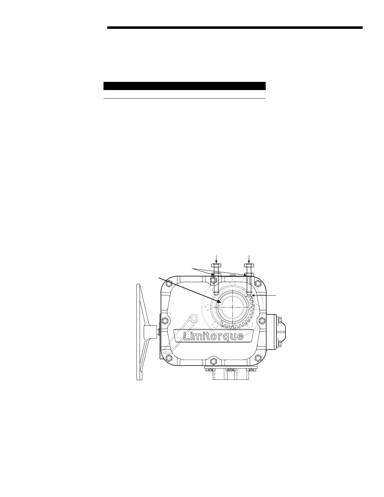
Figure 5.11 – Mechanical Stop Set Screw Adjusted to Torque Drive Nut Contact Point on LY 2001 and 3001
#32 Torque Nut
#59 Locking Nut
#58 Mechanical Stop Screw
Mechanical Stop Screw
CLOSED OPEN
#28 Stop Pin and
Mechanical Stop
Screw positioned
at contact point
LY 2001
3001 To
View
CCW to Open
Flow Control Division
Limitorque Actuation Systems