5-14 LY Installation and Maintenance for LY 1001, LY 2001 and LY 3001 LMAIM1501
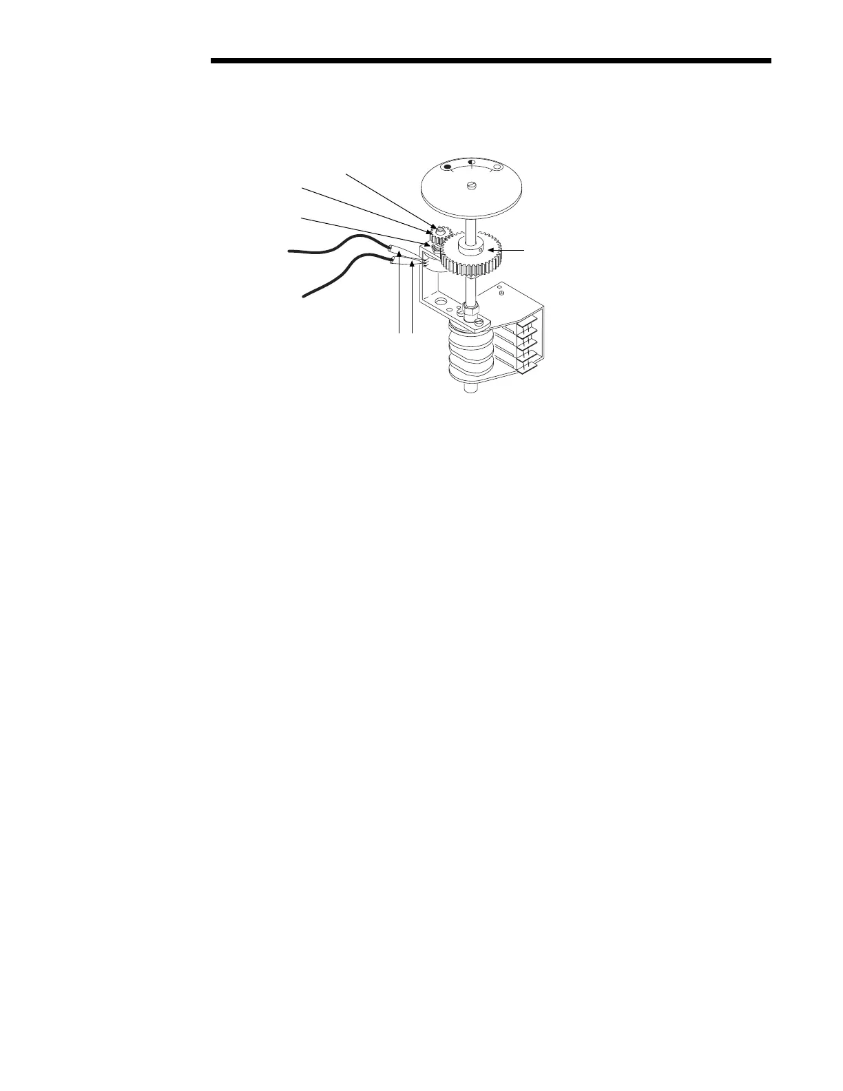
Figure 5.13 – Potentiometer Calibration Components
4. If the reading is not correct, proceed to Step 5. If the reading is correct, proceed to Step 6.
5. a. Loosen the small Set Screw that retains the Spur Gear to the Potentiometer Shaft.
b. Using a small flat-tipped screwdriver in the slotted Potentiometer Shaft, rotate the Shaft until the correct
reading is obtained as described in Step 3.
c. Retighten the Set Screw.
6. Disconnect the ohmmeter and reconnect the Potentiometer wiring to the original connection.
Limitorque
PERCENT OPEN
0
50
100
Potentiometer Shaft
Spur Gear
Setscrew
End Connection
Center Connection
Ohmmeter to Pot Leads
Potentiomete
Drive Gear
Flow Control Division
Limitorque Actuation Systems