6-8 LY Installation and Maintenance for LY 1001, LY 2001 and LY 3001 LMAIM1501
6.5 Motor Operation
CAUTION: Do not force the Declutch Lever into motor operation. Lever will automatically return to motor opera-
tion when the motor is energized.
Piece numbers refer to Figures 6.5, 6.6, and 6.7 for LY 1001, and Figures 6.8, 6.9, 6.10, and 6.11 for LY 2001/3001.
The Motor Pinion Gear (piece #54) turns the Worm Shaft Pinion Gear (piece #53), which is part of the Input Worm
Shaft (piece #31). The Input Worm Shaft drives the Input Worm Gear (piece #18) that is lugged to the Clutch Sleeve
(piece #13). The Input Worm Gear drives the Worm Shaft Assembly through the lugs and splines on the Clutch
Sleeve. The Output Worm (piece #15) on the Worm Shaft Assembly turns the Drive Sleeve (piece #10). The Drive
Sleeve accepts the Torque Nut (piece #32) that is bored and keyed to fit and turn the particular valve stem.
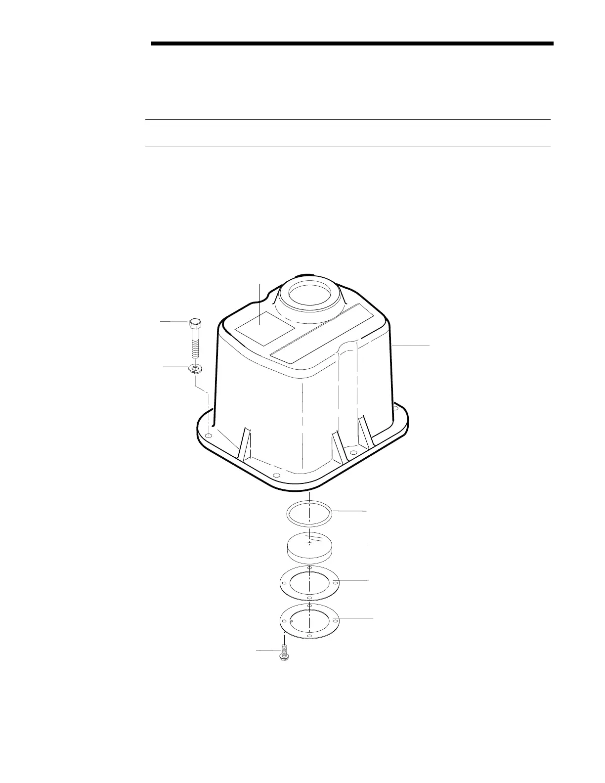
Figure 6.5 – LY 1001 Cover and Associated Parts
Limitorque
Note: Refer to certified data
for construction purposes
01-458-0019-Rev A.
186
67
68
3
86
106
145
109
108
Flow Control Division
Limitorque Actuation Systems