5-2 LY Installation and Maintenance for LY 1001, LY 2001 and LY 3001 LMAIM1501
Table 5.1 – Torque Drive Nut Custom Bore and Keyway Sizes
Unit Type Maximum Bore Maximum Keyway
and Size inch (mm) inch (mm)
LY 1001 1¹₈ dia (28 dia) ¹₄ x ¹₈ (6 x 3)
LY 2001/3001 2³₈ dia (60 dia) ⁵₈ x ⁵₁₆ (15 x 7.5)
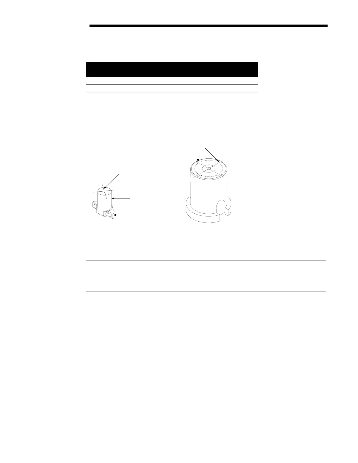
NOTE: Before keywaying, match the Torque Nut with the Valve Stem to ensure proper keyway location. Use the
Keyway Index Mark (LY 1001 only) for locating appropriate keyway location.
Figure 5.2 – LY Keyway Locations
5.3 Installation Overview
CAUTION: Be sure to complete each step of the installation overview before electrically operating your
actuator. If the actuator is already mounted to a valve from the manufacturer, verify that the actuator is
mounted according to the following overview. Failure to follow the installation procedures could result in
personal injury and/or improper operation and could cause damage to the equipment.
1. Mount Torque Nut (piece #32) in the actuator as shown in Figure 5.3 with the following alignment:
A. For LY 1001 – Stop Lugs facing the Actuator Mounting Adapter with index lines positioned to face the
Mechanical Stop Screws.
B. For LY 2001/3001 – Torque Nut axially aligned on the Drive Sleeve so that the bottom of the nut is
positioned inside the Actuator Mounting Base.
A
B
C
D
LY 1001 Keyway
Location Marks
D
A
B
C
Torque Nut
Stop Lug
LY 2001/3001 Keyway
Location Positions
Flow Control Division
Limitorque Actuation Systems