5-4 LY Installation and Maintenance for LY 1001, LY 2001 and LY 3001 LMAIM1501
2. Insert the Retaining Drive Ring (piece #165 for LY 1001, piece #109 for LY 2001/3001) on the Torque Nut
(piece #32) to hold the Torque Nut in place in the actuator.
3. Mount the LY actuator on the mounting flange of the valve or other actuated equipment. High-strength
(minimum SAE-Grade 5 120,000 psi tensile strength) hex head or socket head cap screws with lockwashers
are recommended. The actuator mounting tap quantities and thread sizes are detailed in Table 5.2.
Table 5.2 – LY Actuator/Mounting Base Tap Sizes
Unit Type Tap Size
and Size Quantity English Metric
LY 1001 8 3/8-16 x M10 x 1.5 mm x
0.71 deep 25 mm deep
(Complies with F10 ISO
mounting flange criteria)
LY 2001/3001 8 5/8-11 x M16 x 2 mm x 35 mm
1.26 deep deep (Complies with
F14 ISO mounting
flange criteria)
NOTE: Flowserve has supplied eight taps for the LY 1001, LY 2001, and LY 3001 in English/Metric units to provide
flexibility in mounting arrangements. A minimum of four securing bolts is required to properly secure and retain
torque reaction on these units.
a DANGER: HAZARDOUS VOLTAGE. No electrical power should be connected until all wiring and limit switch
adjustments have been completed. Once power is supplied to unit, exercise caution if cover is not installed.
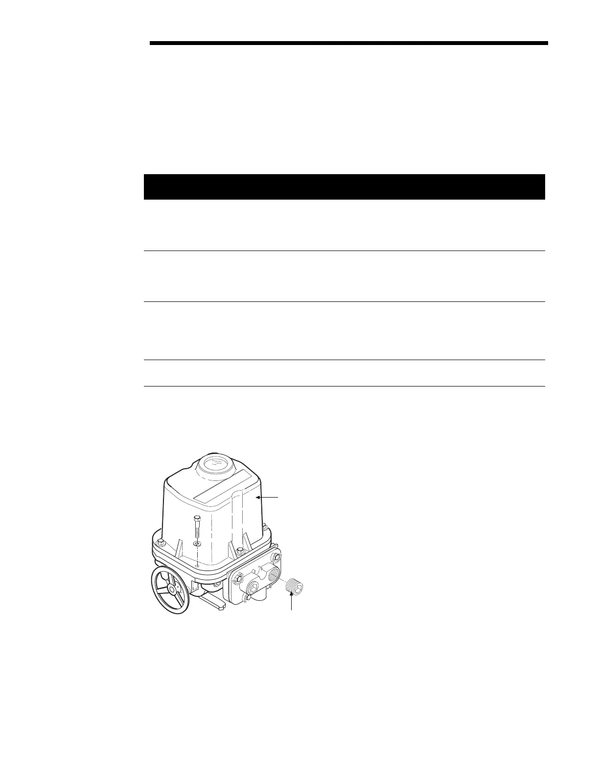
4. Remove the Control Cover (piece #3) and Conduit Pipe Plugs (piece #144).
Figure 5.4 – Removing Control Cover and Conduit Pipe Plugs
Limitorque
#3 Control Cover
#144 Conduit Pipe Plugs
Flow Control Division
Limitorque Actuation Systems