7-4 LY Installation and Maintenance for LY 1001, LY 2001 and LY 3001 LMAIM1501
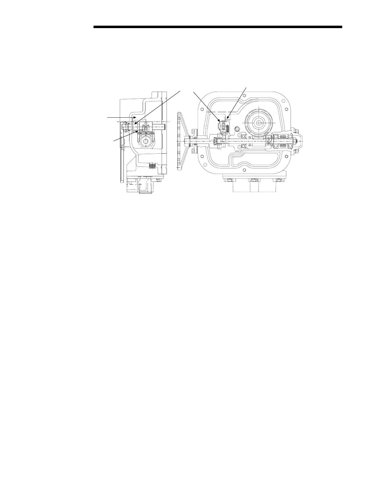
Figure 7.1 – LY 1001 Declutch Return Spring Installation Position
4. Install Declutch Assembly (piece #46, 123, 44, and 55).
5. Install O-Ring (piece #138) over Declutch Shaft (piece #44).
6. Install Declutch Lever (piece #45) and Roll Pin (piece #121).
Install Drive Sleeve
7. Install Drive Sleeve (piece #10).
8. Install Ball Bearing (piece #33) and O-Ring (piece #129) on the Drive Sleeve.
Install Worm Shaft Assembly
9. Install Worm Shaft Assembly.
NOTE: Push the Worm Shaft Assembly through to about 1/2" past the Input Worm Gear for installing the
Clutch Sleeve (piece #13).
Install Handwheel Assembly
10. Install the Clutch Sleeve (piece #13), ensuring the Declutch Fork Assembly (piece #46) is between the Input
Worm Gear (piece #18) and the Clutch Sleeve (piece #13).
11. Install Thrust Washer (piece #26), Thrust Bearing (piece #27), and second Thrust Washer (piece #26) into the
Handwheel Clutch (piece #16).
12. Put a light coat of grease on the Thrust Bearing. Install Spring (piece #154) into the Handwheel Clutch.
13. Install Handwheel Clutch Assembly (pieces #16, 154, 26 [2 pcs], and 27) into the Housing. Push remaining
Worm Shaft Assembly into the Handwheel Clutch of the Handwheel Clutch Assembly.
14. Install O-Ring (piece #135) over the Worm Shaft Assembly Bearing.
15. Install Disc Spring Cap (piece #5) and Hardware (pieces #61 and 62).
16. Install Handwheel Cap Gasket (piece #137) and Handwheel Assembly (pieces #41, 112, 34, 137, 134, 155
[2 pcs], 154, 70, and 37).
17. Install Hex Head Cap Screw and Lockwasher (pieces #63 and 64).
6301.6301.
Rib
Bottom
Declutch
Fork
LY 1001 End View
#47 Declutch
Return Spring
Rib
LY 1001 Top View
Flow Control Division
Limitorque Actuation Systems