01-472-0007-3
SMB/SB Installation and Maintenance Manual 140-11000 • July 2003 4-6
Flow Control Division
Limitorque Actuation Systems
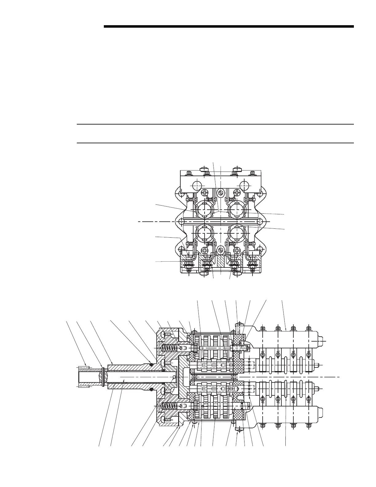
4.4.2 Four-Train Geared Limit Switch
The rotor-type, four-train geared limit switch employs four rotary drum switches. Each rotary drum switch contains four contacts.
When the rotor is properly set to trip at the desired position, two of these contacts open electric circuits and two of the contacts close
electric circuits. One rotor is set to trip at the full open position of the valve, and one rotor is set to trip at the full close position of the
valve. The other two rotors are set at some intermediate position depending on the application.
For the geared limit switches to trip at any desired position, follow the steps in Section 4.4.1, Two-Train Geared Limit Switch, with
the exception that the piece numbers refer to Figure 4.2 and Table 4.4.
NOTE: The upper Set Rod (piece #48) allows adjustment of the two adjacent upper rotors, and the lower Set Rod (piece #48) allows
adjustment of the two adjacent lower rotors.
Figure 4.2 – Four-Train Geared Limit Switch – Rotor-Type