SMB/SB Installation and Maintenance Manual 140-11000 • July 20038-16
Flow Control Division
Limitorque Actuation Systems
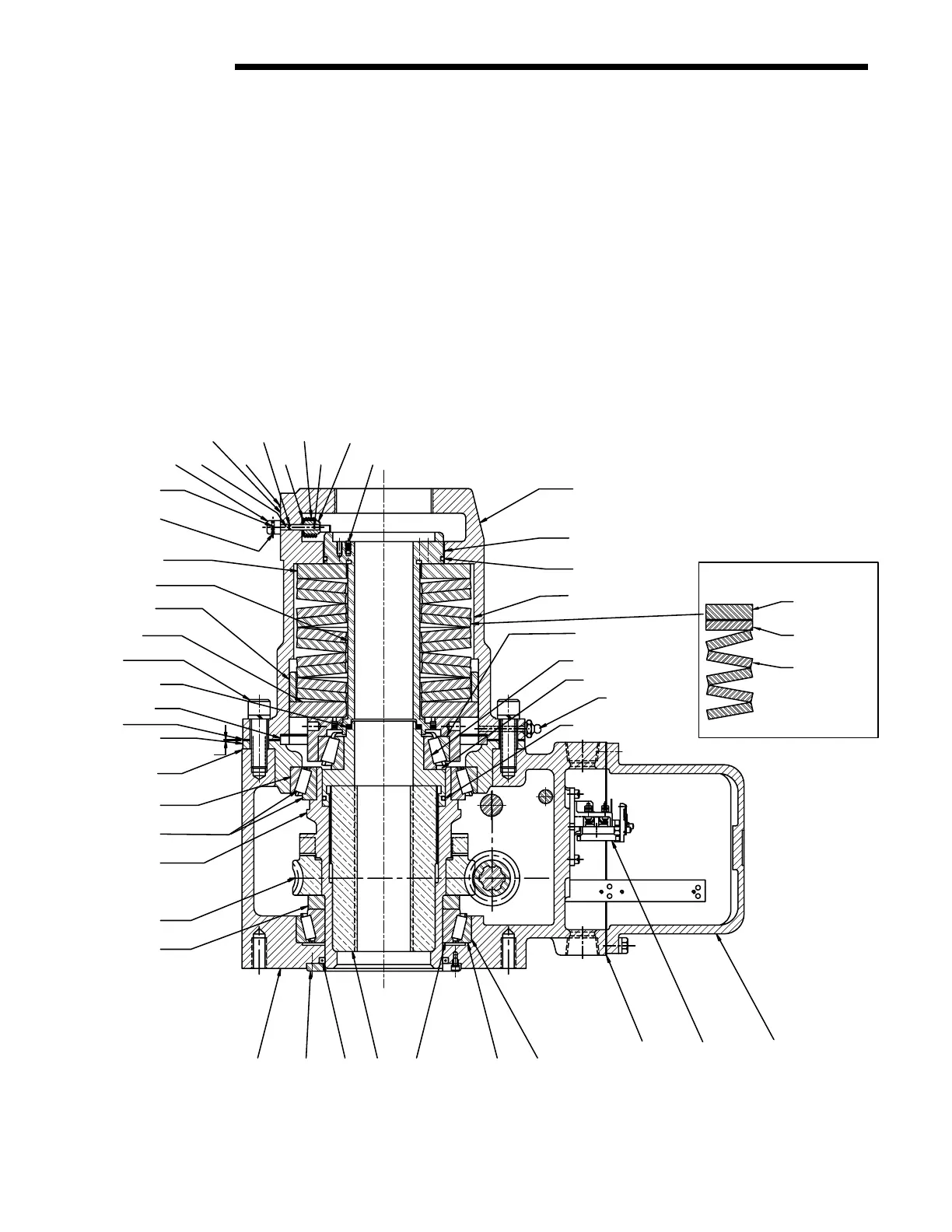
b. If the actuator is mounted on the valve, thread the Stem Nut (piece #20) down the stem until the splines hit. Put the actuator in
manual operation. Rotate the Handwheel in the direction to move the stem upward—usually the open direction. The Stem Nut
will lower as the Handwheel turns, until it bottoms out on the shoulder in the Drive Sleeve and the stem starts to move up.
2. Replace the Bearing Cartridge (piece #154) and the Bearing Cup and Cone (pieces #147 and #148). Ensure Quad Ring (piece
#168) and O-Ring (piece #163) are properly installed. Ensure the Bearing Cartridge engages the splines on the top of the Stem
Nut—the Bearing Cartridge will not rotate if engaged properly.
3. Replace the Centering Ring (piece #167).
4. Replace the Spring Cartridge (piece #149) as an assembly along with the Belleville Springs (piece #152), Thrust Washers
(pieces #150 and #153), and Spring Retainer Cap (piece #166).
5. Replace the Deflection Limit Sleeve (piece #161).
6. Verify that the O-Ring (piece #160) is properly installed in the Spring Retainer Cap (piece #166). Install the Spring Housing
(piece #140), adding a gasket for sufficient thickness to fill in the gap “a,” making an allowance for the gasket material
compressibility.
Figure 8.5 – SB-3 Parts Diagram