SMB/SB Installation and Maintenance Manual 140-11000 • July 20034-17
Flow Control Division
Limitorque Actuation Systems
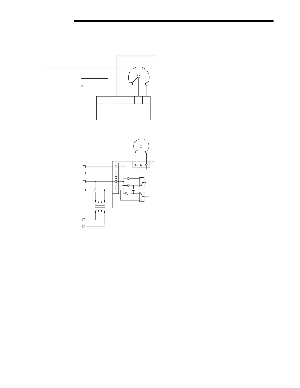
Figure 4.8 – Typical Connection for R/I Signal Converter (Older Version)
Figure 4.9 – Typical Connection for PT20SD R/I Converter
4.7 Additional Electrical Components
4.7.1 Reversing Starter
The reversing starter electrically changes the operation of the electric motor from one direction of rotation to the other. The starter
consists of two contactors mounted on a common base and mechanically interlocked.
Each contactor consists of the following:
• three normally open power contacts
• one normally open circuit holding contact
• one normally closed interlock
• one magnetic holding coil
The starter can be provided two ways:
• Mounted within the actuator limit switch compartment
• Supplied in a separate enclosure
4.7.2 Overload Relays
Overload relays de-energize the holding coils of the reversing starter, which open the power contacts to de-energize the electric motor.
The relays function at a predetermined current value and can reset either automatically or manually as follows:
• Reset automatically if mounted as detailed in Figure 4.10.
• Reset manually if the reversing starter is furnished separately.
The relays are sized in accordance with full load (running) motor current.
4.6.3, pg. 4-15.