EasyManuals Logo

Limitorque SMB-5T User Manual

Default Icon
96 pages
To Next Page IconTo Next Page
To Previous Page IconTo Previous Page
Page #27 background imageLoading...
Page #27 background image
SMB/SB Installation and Maintenance Manual 140-11000 • July 2003 4-18
Flow Control Division
Limitorque Actuation Systems
4.7.3 Control Station
The control station consists of
•a five-position Local-Stop-Off-Stop-Remote selector switch, padlockable in each position
•a spring return Open-Close selector switch
•green and red LED lights for position indication.
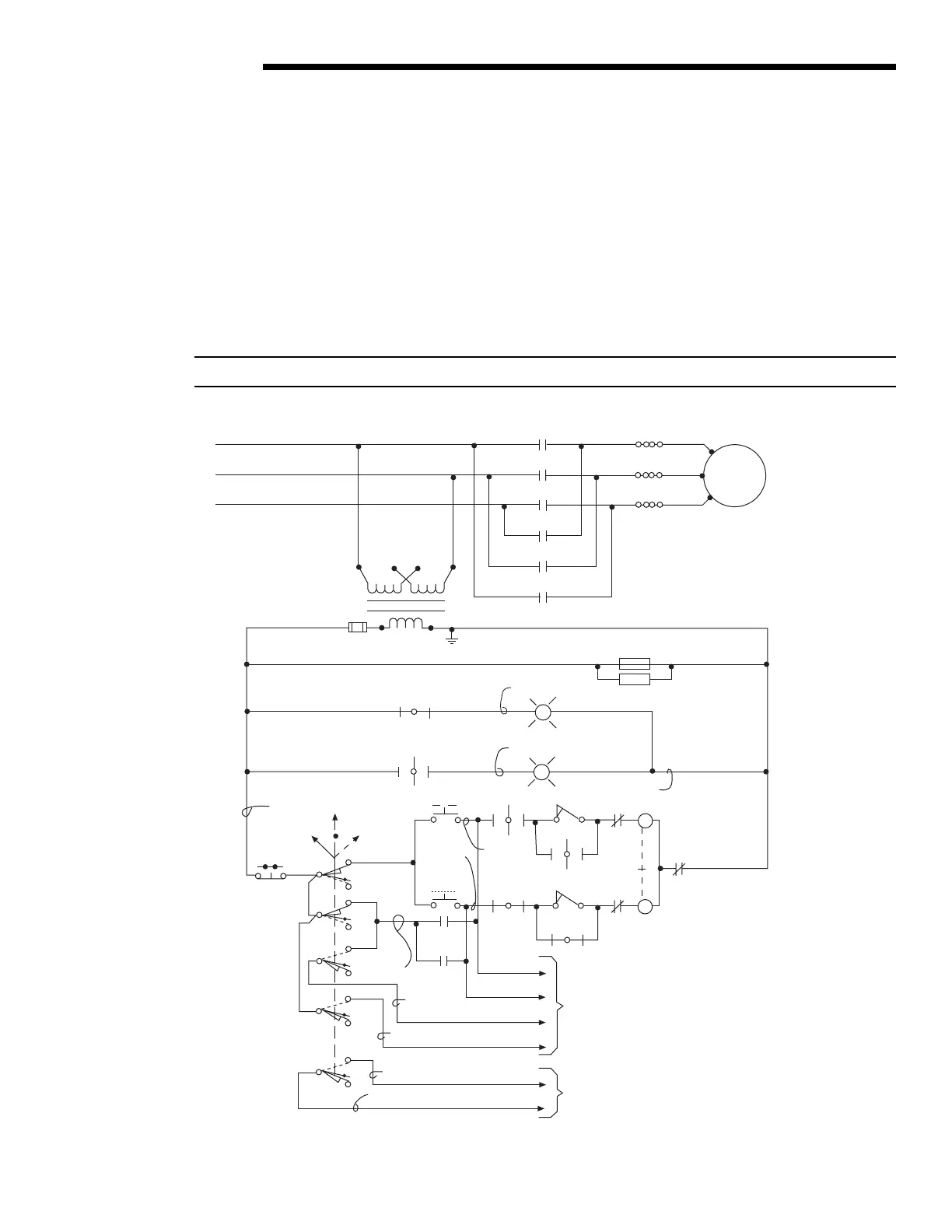
Typical wiring of the control station in conjunction with the motor control circuit is shown below in Figure 4.10.
Figure 4.10 – Typical Wiring Diagram—Built-in Reversing Starter and Control Station for a Three-Phase Power Supply
NOTE: Current design. Earlier control wiring varies slightly.
L1
L2
L3
M1
M2
M3
OL
OL
OL
Motor
T1
T2
T3
CL2
CL2
C
C
C
o
o
o
(H1)(H3) (H2)(H4)
CL1
CL1
CL1
CL1
60
70
7
3
SS
OFF
Black
LOCAL
REMOTE
PB2
STOP
CL1
Red
Green
CL2
CL2
OL
White
Yellow
Blue
PB1
OPEN
CPT
FUSE
(X1) (X2)
HTR1
HTR2
4
43
18
45
47
C
o
C
o
5
8
5
Brown
Orange
Pink
REMOTE (31)
REMOTE (30)
Gray
5
5
9
31
30
3
11
3
7
PB3
CLOSE
53
41
5
Purple
STOP (9)
COMMON (11)
CLOSE (51)
OPEN (41)
1
17
55
57
2
To customer’s
equipment
Remote
indication
if required
51

Table of Contents

Questions and Answers:

Question and Answer IconNeed help?

Do you have a question about the Limitorque SMB-5T and is the answer not in the manual?

Limitorque SMB-5T Specifications

General IconGeneral
BrandLimitorque
ModelSMB-5T
CategoryController
LanguageEnglish

Related product manuals