Rev: 12.28.22 Page 4 CCD-0004051
Prior to Installation
Make sure that all components i.e., bed frame rails, wood slats, motor mount, drive shaft and center support,
are all cut to the proper dimensions prior to installation.
Holes depicted in the components indicate where fasteners will be needed including self tapping fasteners.
Installation
Bed Frame Assembly
NOTE: The dimensions of each Smart Bed Lift will differ in size and some components but the bed frame
assembly instructions will be close to the same for every Smart Bed.
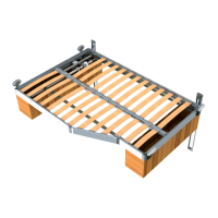
1. Locate two end rails (Fig. 1A), side rails (Fig. 1C), corner cap keys (Fig. 1B), if applicable, Smart Bed Lift
joint assembly parts (Fig. 1E), bendable flat bracket (Fig. 1D) and place in a clean. flat, work area.
2. Place the plastic corner cap keys (Fig. 1B) at each corner. If applicable, Smart Bed Lift joint assembly
parts and bendable flat bracket at the desired angles.
3. Place the rails into the desired shape with the slat insert channel facing towards the bed area with the
channel extrusion facing up. (Fig. 1F).
Resources Required
• Cordless or Electric Drill or Screw Gun
• Pneumatic Rivet Gun With Extended Tip
• Pneumatic Staple Gun
• Appropriate Drive Bits
• Appropriate Drill Bits
• Hex Key (4mm)
• Socket Wrench (8 mm)
• Rubber Mallet
• Super Lube® Grease
• High Strength Red Loctite
• Tape
• Pencil
Fig. 1
A
B
C
C
A
D
E
F
 Loading...
