Rev: 12.28.22 Page 18 CCD-0004051
Drive Shaft Centering Bracket
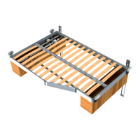
1. Measure from the outside end rail to the end of the drive shaft header center brackets (Fig. 34A) with
the supplied measurements for each Smart Bed Lift model. Move the long and short drive shaft header
center brackets into place so that both sides are even.
2. Loosely attach the long and short drive shaft header assembly centering bracket (Fig. 34A) to the
side rail mounting channel brackets (Fig. 34B) with two nuts (Fig. 34C).
3. Tighten the nuts completely after the motor mount support and motor mount bracket have
been installed.
Motor Mount Support and Bracket
1. Place the motor mount support bracket (Fig. 35A) onto the center rail support (Fig. 35B) and the
inner channel of the side rail (Fig. 35C) just in front of the drive shaft centering bracket (Fig. 34A),
towards the end rail.
2. Place the motor mounting bracket (Fig. 36A) on top of the motor mounting support (Fig. 35A).
Fig. 34
A
C
B
D
D
Fig. 35
A
B
C
C
E
 Loading...
