CHAPTER 4: ELECTRICS 4-19
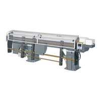
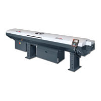
ALPHA 538/552
4.2. CONNECTIONS
(11) Power supply
Voltage: 3 x 220-480 V, 50 / 60 Hz + Ground (± 10%)
Maximum voltage: 3 x 220 V = 6 A
3 x 480 V = 3 A
Before connecting, check to make sure that the voltage of the bar feeder corresponds to
the one provided by the lathe. The voltage of the bar feeder is indicated on the
identification plate.
a) Transformer T1
b) Hydraulic pump motor
The LNS bar feeders are equipped with their own thermal protection systems (breakers, thermal relays
and fuses, etc.). The power supply for the bar feeder should be connected to the output of a breaker
mounted in the electrical control box of the lathe (10 A max.).
For the wiring inside the lathe, the section of the cables should be at least 1.5 mm
2
(AWG 16).
(12) Signals from the lathe to the bar feeder
Always refer to the electrical diagrams shipped with the bar feeder and placed in the electrical cabinet.
· All wires for interface connections are numbered
· All bar feeders are equipped with a power supply of +24 DC.
a) 24 V DC power supply
This corresponds to the +24 V of the bar feeder. This power shall be used to connect the signals from the
lathe to the PLC.
· All signals from the lathe to the PLC shall be powered by the +24 V DC of the bar feeder.
· All signals from the bar feeder to the lathe shall be powered by the +24 V DC of the lathe.
For the other types of connections, please contact LNS S.A., or their local representative.
b) "EMERGENCY STOP" signal of lathe XT8-XT9
This signal is part of a safety link (Emergency Stop circuit) of the bar feeder. XT8-XT9 corresponds to the
Emergency Stop signal of the lathe. If the circuit is open, the bar feeder will go into an Emergency Stop
mode.
When the lathe is in an Emergency Stop mode, or if the safety line of the bar feeder is interrupted, an
alarm will go off and the R1 relay of the bar feeder will be triggered (see description of the R1 relay,
below).
c) Lathe clamp signal (PLC input A1)
This signal is for checking the mode of the lathe clamping device (open), and is mainly used for the
feeding of a part, which takes place each time the clamp opens.
For safety reasons, wire a normally open contact, coming from the signal of the lathe
clamp. A clamp open signal must be selected.
d) Lathe in automatic cycle (PLC input A2)
This signal indicates that the lathe is in automatic cycle.
e) Load command (PLC input A3)
Should the lathe be equipped with a sub-spindle or the lathe is of twin spindle type, should the part
require multiple feeds, this signal will be used as a load command from the lathe.
For safety reasons, and to prevent collisions between the part being transferred to the second spindle
and the newly loaded bar stock when there is a simultaneous loading, the lathe must control the loading
of a new bar.