8-18 CHAPTER 8: OPERATION
ALPHA ST320 S2
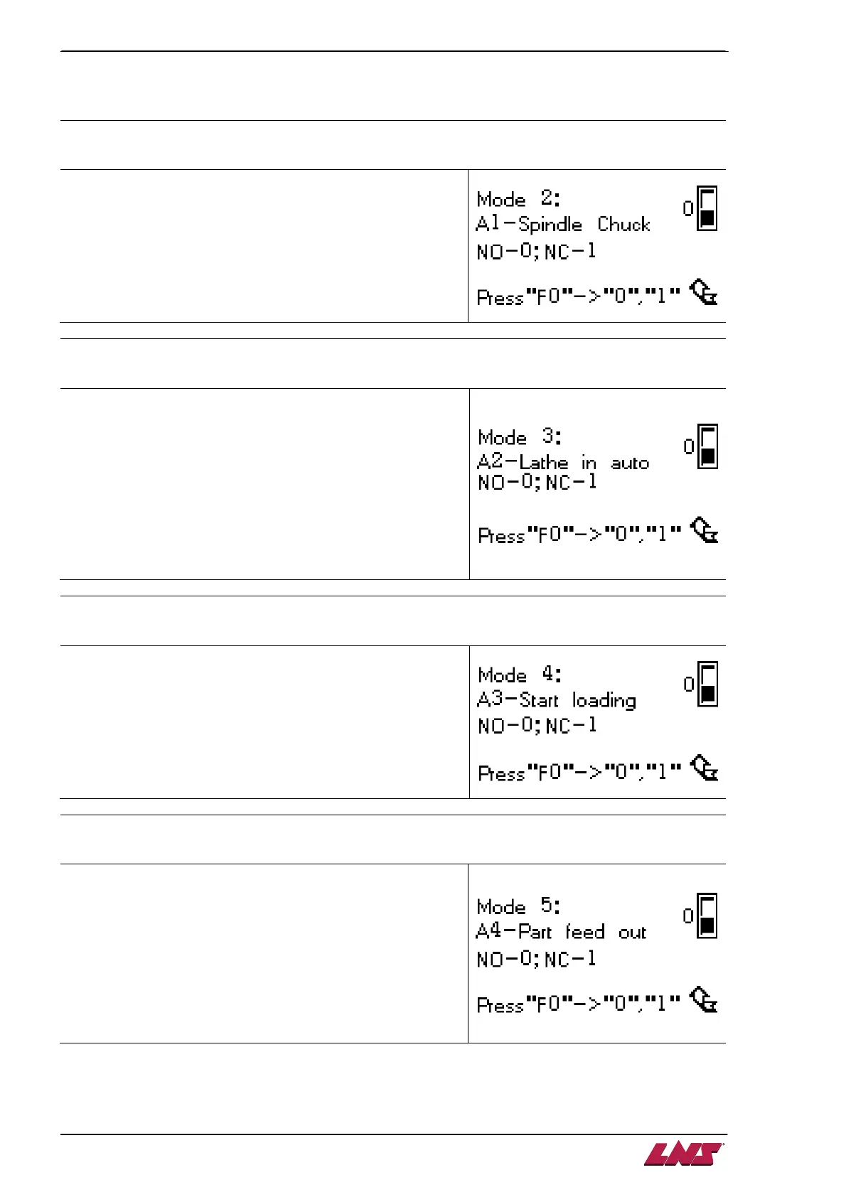
Note: MODE 2, 3, 4, 5, 28, 29 and 30 are related to interface logic setup. Those parameters are only
available when related interface wires are connected accordingly.
MODE 2
:
::
:
Chuck signal (A1) logic setup
0 - CHUCK signal is ON when chuck is open
1 - CHUCK signal is OFF when chuck is open.
MODE 3
:
::
:
CNC auto signal (A2) logic setup
Bar feeder must receive the A2 signal before being putted in
auto mode
0 – Lathe auto signal (A2) is activated when the lathe is in
auto mode (i.e. receiving A2 for allowing “all pushing forward
actions”)
1 – Lathe auto signal (A2) is activated when the lathe is in
auto mode (i.e. receiving A2 for not allowing “all pushing
forward actions”).
Note:
MODE 4
:
::
:
Start loading Signal (A3) logic setup
0 – When the START LOADING signal is ON, the loading
cycle is initiated.
1 – When the START LOADING signal is OFF, the loading
cycle is initiated.
MODE 5
:
::
:
Pushing Signal (A4) logic setup 1of 2
The pushing signal allows the lathe to control the pushing
force during machining operations.
0 –
Pushing signal (A4) prohibits pusher forward actions
during machining
(If the lathe don’t provide A4, mode 5=0)
1 – Pushing signal (A4) allows pusher forward actions during
machining
 Loading...