CHAPTER 6: HYDRAULICS 6-3
ALPHA ST320 S2
2. DESCRIPTION OF THE ELEMENTS
2.1. Hydraulic pump motor M2
The hydraulic pump is powered by 3 phases 220V AC. The hydraulic pump powers on immediately when
conditions below satisfied:
− The bar feed system switched to automatic mode.
− The guide channel is closed.
− The pusher position is located between home position the “2nd” of parameter P06.
The hydraulic oil is injected into the guiding channels and filling the space between the rotating bar stock
and guiding channel. Once the pusher exceeds “2nd” position of parameter P06 or the bar feed system
switched to manual mode. The hydraulic pump powers off.
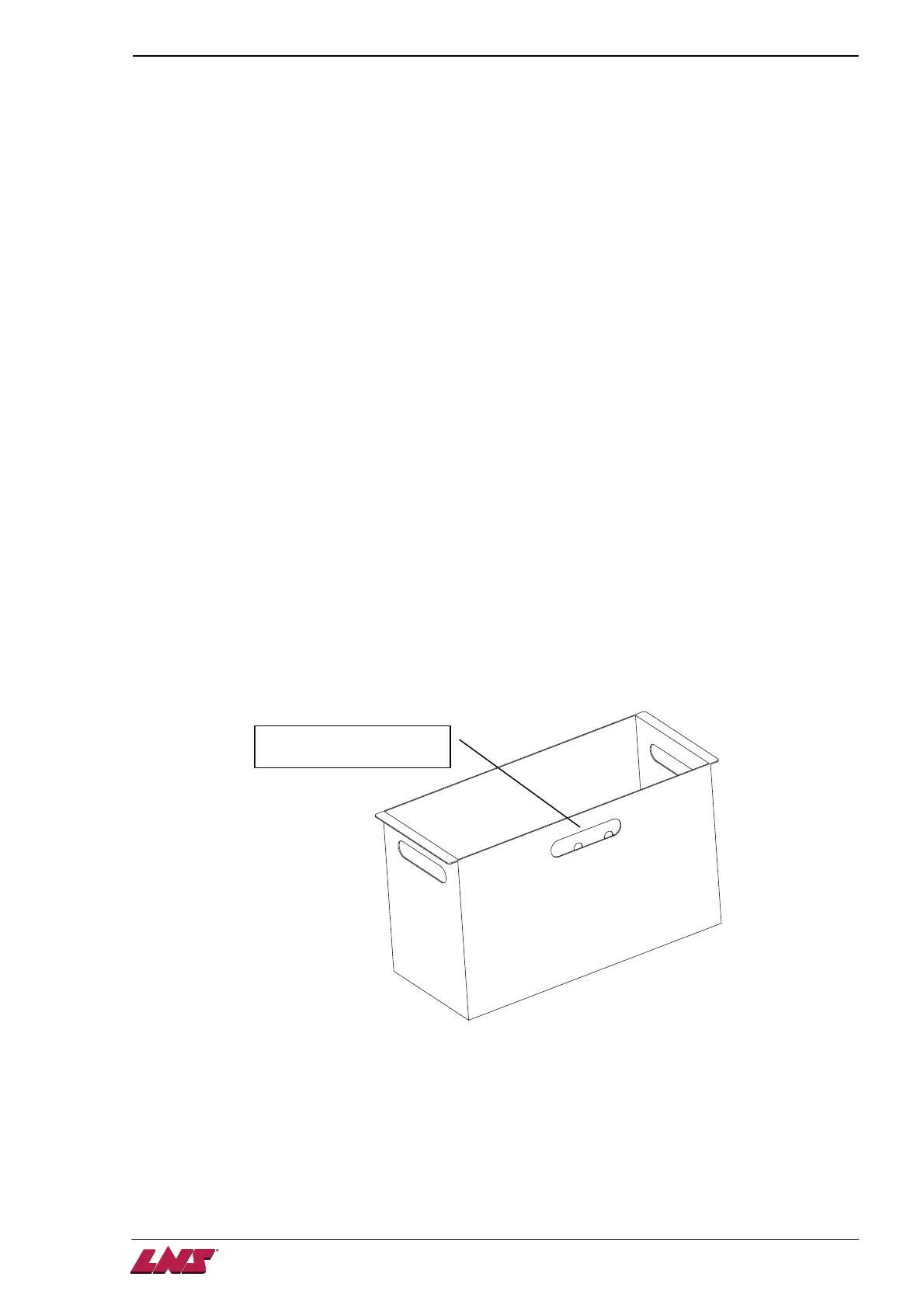
2.2. Remnant tray
The tray gathers remnants removed by the material clamping device. It is located between the bar feeder
b
ody and oil tank. The maximum available remnant length is 300mm.
The available capacity of the tray depends on remnant diameter and length. The tray should be checked
and emptied regularly to make sure the tray is not overfilled. An overfilled remnant tray might cause
problems below:
1. The recycled oil might be interrupted and spill out.
2. The remnants might be lying between the material clamping space and interrupt the next bar stock
insertion.
3. The tray might be too heavy to be moved.
It is recommended to keep the height of the remnant hip under the opening.
 Loading...