7-16 CHAPTER 7: GENERAL DESCRIPTION
ALPHA ST320 S2
7. BAR LENGTH MEASURING DEVICE
The TOP CUT position is defined by the position of the bar tip machining process applied on a new bar
stock right after it’s loaded into the lathe. The purpose is to get a qualified tip surface able to serve as a
reference for positioning bar stock during machining. Generally, this process will be proceed in the bar
change sub-program and only do once for each bar. Depending on the tooling layout, this position could
be placed on any position outside the lathe chuck (mostly 30 to 50mm from the lathe chuck surface).
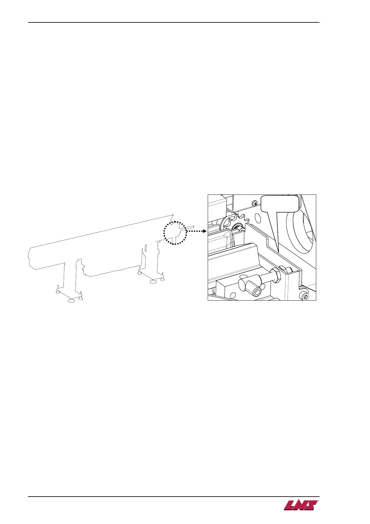
The bar length measuring device serves to measure the distance that a bar stock is being pushed out of
the bar feeder. During bar feeder loading cycle, the bar length device cylinder is activated and positions a
flap on front opening of the guiding channel as soon as the loading fingers are activated. When the bar
feed system advances the bar stock forward and the bar tip hits the flap, the PLC reads the signal from
the bar length device sensor and starts to measure the bar stock moving distance. When the bar tip
arrives in TOP CUT (P05) position, a START signal will be sent through relay A2 to the lathe. Then the
pusher either keep moving forward or holds at the position according to the service parameter set up.
Since the bar length measuring sensor is only activated by the bar tip, please note that the TOP CUT
distance is independent from the bar stock length. Once the bar feeder position is fixed, the TOP CUT
position is only related to the distance from the bar feeder to the lathe chuck surface.