9. Miscellaneous
9 Miscellaneous
9.1 Emissions System Functionality
GENERAL EMISSIONS DISCLAIMER This panel may include provision(s)
for operator input such as FORCE REGENERATION, INHIBIT REGENER-
ATION, INTERLOCK, and others specific to US and International emissions
regulations. Responsibility for emissions related inputs and compliance
with emissions regulations is solely that of the owner and/or operator of the
machine/engine on which this panel is connected.
CAUTION Carefully read and understand the engine manufacturer
owner/operator manual. Your engine manufacturer provides specific in-
formation regarding the exhaust emission system of your engine. This
information is maintenance, procedural, and safety related. Failure to
exactly follow the engine manufacturer instructions and schedules could
potentially result in harm or injury to you and/or others. Further, failure to
exactly follow the engine manufacturer instructions and schedules could
result in damage to your engine and/or equipment.
The LOFA CANplus
®
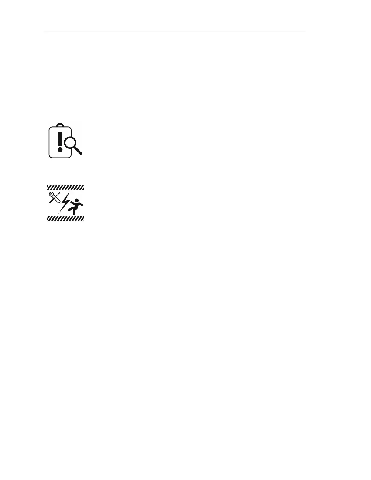
display reports emissions messages received from the engine ECU. Depending
on the received message, icons or symbols may be displayed on the screen. Some messages/icons
are displayed as an overlay (inhibit symbol shown at left). Other symbols/icons may cover most of the
screen. The operator MUST respond to the indications on the display following engine manufacturer
recommended procedures/actions. Please note that indications shown by the display may vary with
respect to engine manufacturer and may vary between engine models from the same manufacturer.
9.2 CP1000 Panel Wiring
Most electronically governed engine installations include a harness with built in J1939 backbone.
Use twisted shielded pair with a drain wire for CAN wiring terminated with 120Ω resistors at each
end. The maximum length for the CAN bus is 131 feet (40 m) and stubs should not exceed 39 inches
(1m) in length.
9.2.1 Typical J1939 Wiring Topology
Page 36 LOFA document No. 463-3002-59 Page 36