G120F/G160F/G200F Part IV Disassembly and maintenance
- 48 -
a) Coat the reamer and valve guide with cutting oil.
Rotate the reamer clockwise through the valve guide the
full length of the reamer.
Continue to rotate the reamer clockwise while removing it
from the valve guide.
Tool: valve guide reamer
b) Thoroughly clean the cylinder head to remove any
cutting residue.
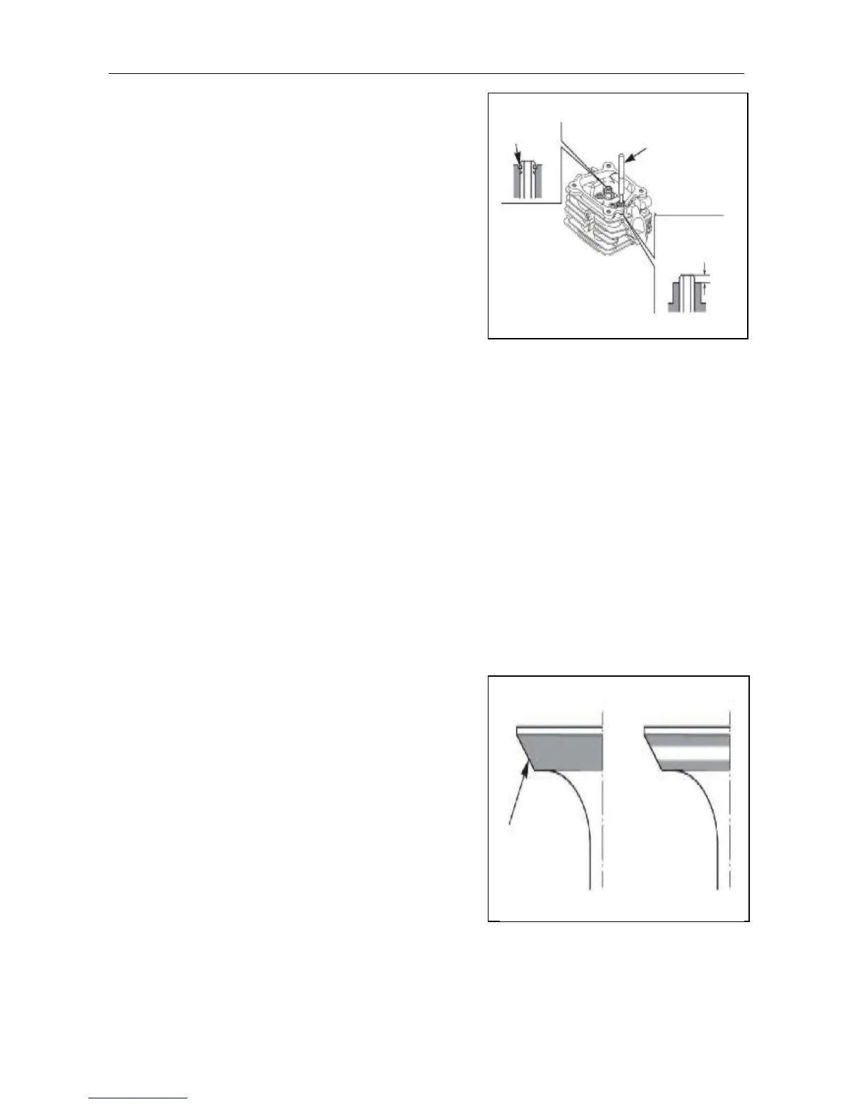
c) Check the valve guide bore; it should be straight,
round and centered in the valve guide. Insert the valve
and check operation. If the valve does not operate smoothly, the guide may have been bent
during installation. Replace the valve guide if it is bent or damaged.
d) Check the valve stem-to-guide clearance.
e) Stem –to- guide clearance: Subtract each valve stem OD from the corresponding guide ID to
obtain the stem -to- guide clearance.
f) If the stem-to-guide clearance exceeds the service limit, determine if the new guide with
standard dimensions would bring the clearance within tolerance. If so, replace the guide as
necessary and ream to fit. Recondition the valve seat whenever the valve guide is replaced.
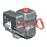
5) Valve seat:
a) Thoroughly clean the combustion chambers and
valve seats to remove carbon deposits. Apply a light
coat of red lead power or erasable color on the valve
faces.
b) Insert the valve, and then lift them and snap them
close against their seats several times. Be sure the
valve does not rotate on the seat. The transferred
marking compound will show any area of the seat that
is not concentric.
Guide
clip
Valve
guide
driver