G120F/G160F/G200F Part IV Disassembly and maintenance
- 49 -
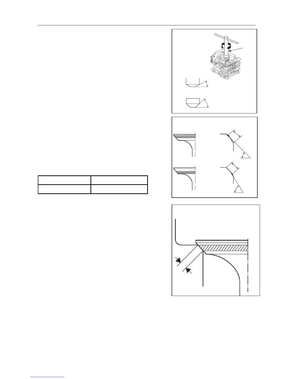
c) Use a 45°cutter, remove enough material to produce a
smooth and concentric seat. Turn the cutter clockwise,
never counterclockwise.
Tool: valve lapper
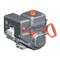
d) Use the 32°-45° and 60° cutter to narrow and adjust
the valve seat so that it contacts the middle of the valve
face.
The 32° cutter removes material from the top edge
(contact too high).
The 45° cutter removes material from the bottom edge
(contact too low).
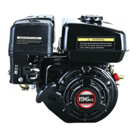
Bu sure that the width of the finished valve seat is within
specification.
Standard Service limit
0.8mm 2.0mm
e) Make a light pass with the 45° cutter to remove any
possible burrs at the edges of the seat.
f) After resurfacing the seats, inspect for even valve
seating.
Apply a light coat of Prussian Blue or erasable marker ink
on the valve faces. Insert the valves, and then lift them
and snap them close against their seats several times. Be
sure the valve does not rotate on the seat.
The seating surfacing, as shown by the transferred
marking compound, should have good contact all the way
around.
g) Apply lapping compound on the valve face, and use a hand valve lapper to recondition the
valve seat.
h) After reassembly, check and adjust the valve clearance.
0.8mm
Valve lapper