Basic Setup (DV700 Series)
6
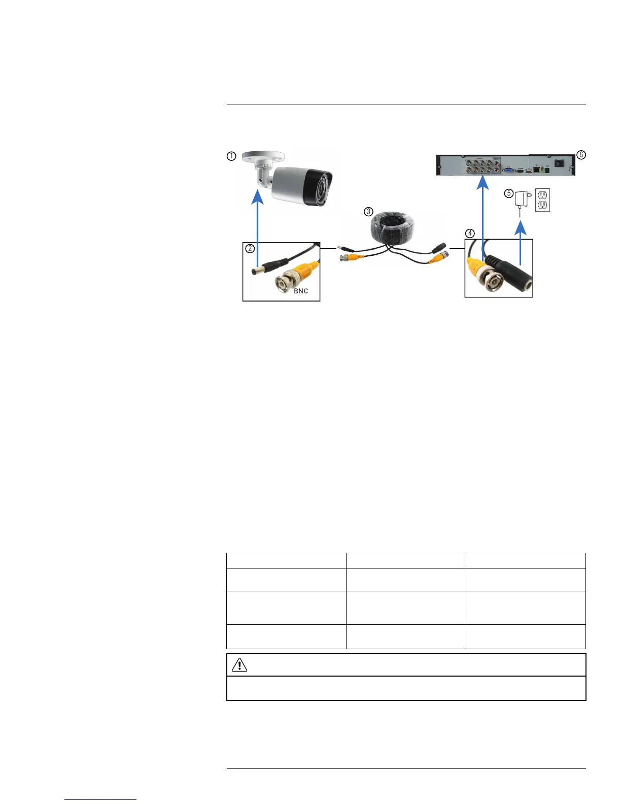
Camera Installation Diagram
1. Camera.
2. End of extension cable with male power connector.
3. Extension cable.
4. End of extension cable with female power connector.
5. Camera power adapter.
6. DVR.
6.11.4.1 Connecting and Removing BNC Cables
BNC (Bayonet Nut Connector) is a special connector that locks on to the system port and
cannot be accidently removed.
To connect or remove a BNC connector:
• Push the BNC connector firmly into the BNC port and simultaneously twist the connec-
tor clockwise to tighten.
• To remove a BNC connector from a BNC port, push and simultaneously twist the con-
nector counter-clockwise to loosen the BNC connector.
6.11.5 Extension Cable Options
You can extend the cable run for your camera depending on the cable type used. Addition-
al extension cables sold separately. See table below:
Option Cable Type Max Cable Run Distance
1
Lorex model MCBL-60BNCU
BNC Cable
60ft / 18m
2
‘RG59’ or ‘Coax’ or ‘Coaxial
BNC’ Siamese (Video and
Power)
300ft / 92m
3
‘RG59’ or ‘Coax’ or ‘Coaxial
BNC’ (Video Only)
800ft / 242m
CAUTION
The extension cable must be a single stretch of cable between the DVR and camera. You cannot connect
multiple extension cables to each other.
#LX400060; r.30328/30328; en-US
14