ASSEMBLY
OM 0467SB-A [14]
Installation of the Manual Rotation Support on the Tractor
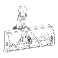
1. Figure 3: Disconnect the female quick couplers
(item 1) from the tractor valve and install the
protective caps. And install the protective caps
on the male quick couplers of the tractor valve.
2. Figure 3: Remove the M8 hex bolt (item 2) in
the center of the four male quick couplers of the
tractor valve.
3. Figure 3: Remove the attachment plate
(item 3) from the male quick couplers of the
valve.
4. Figure 3: Remove the threaded bolt (item 4)
that secures the right side of the hood to the
tractor frame.
NOTE : Items 2, 3, 4 removed on previous
steps will not be used.
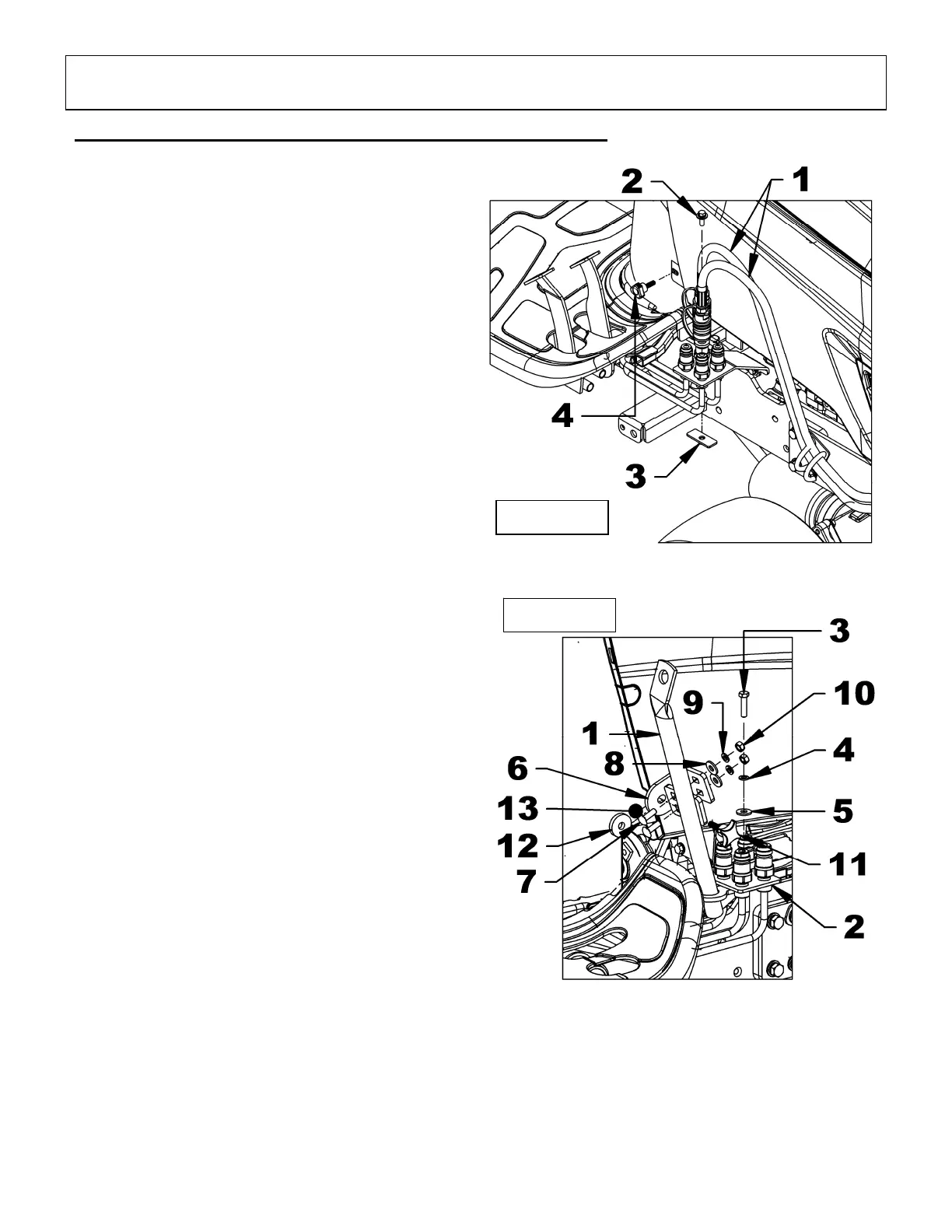
5. Figure 4: Insert the handle support (item 1)
under the quick coupler bracket of the valve
and between the four quick couplers. Secure
the handle support (item 1) with a 5/16"NC x
1 1/4" hex bolt (item 3), a 5/16" lockwasher
(item 4) and a 5/16" flat washer (item 5).
6. Figure 4: Secure the handle support bracket
(item 6) to the handle support (item 1) with two
5/16" x 1" carriage bolts (item 7), 5/16 "flat
washers (item 8), lockwashers 5/16" (item 9)
and 5/16" hex nuts (item 10) DO NOT
TIGHTEN.
7. Figure 4: Attach the handle support bracket
(item 6) and spacer (item 12) to tractor frame
(item 13) with a M8 x 1.25 x 30mm "X" knob
(item 11).
8. Figure 4: Tighten both hex nuts 5/16"
(item 10).
9. Figure 3:
Remove the protective caps on the
male quick couplers. Remove the protective
plugs from the female quick couplers. Connect
the female quick couplers (item 1) to the tractor
valve.
Figure 3
Figure 4