ASSEMBLY
OM 0467SB-A [15]
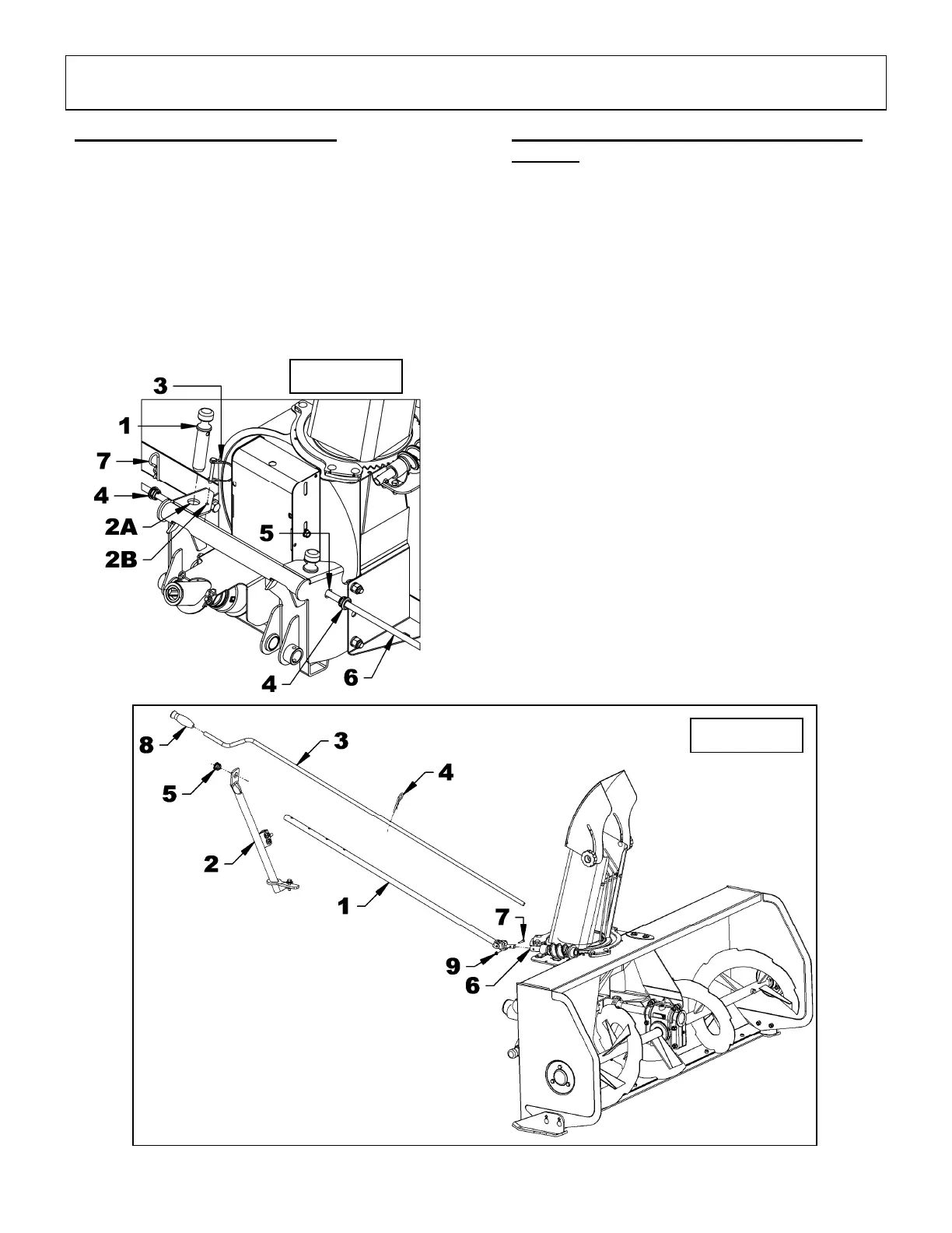
Figure 5
Figure 6
Storing Pins and the Handle
1. Figure 5: Figure 5: Insert the pins 1 "x 3 7/8"
(item 1) into the holes (item 2A) of the
snowblower hitch. Insert the 1/4" round wire lock
pins (item 3) into the holes (item 2B) of the
snowblower hitch.
2. Figure 5: Install one guide (item 4) in each hole
(item 5) on each sides of the hitch.
3. Figure 5: Insert the handle (item 6) in the two
guides (item 4) and secure with the hairpin
(item 7).
Installation of Manual Rotation on the
Tractor
1. Figure 6: Insert the plastic grommet (item 5)
in the upper hole of the handle support
(item 2).
2. Figure 6: Attach the assembled rotation tube
(item 1) to the rotation worm (item 6) by
inserting the fork and secure in place with a
allen socket head capscrew 10-24 NC x 1"
(item 7) and a 10-24 NC nylon insert locknut
(item 9).
3. Figure 6: Install the plastic handle (item 8)
on the rotation handle (item 3) and tighten all
bolts.
4. Figure 6: After completing the "Installation
on the Tractor" step, insert the rotation
handle (item 3) in the handle support
(item 2) and the rotation tube (item 1) and
secure with a 4mm x 80mm hairpin (item 4).


 To Next Page